
Key Takeaway: Successfully replacing or standardizing an industrial limit switch with the Kacon KXL Series requires evaluating more than outer appearance. Engineering compatibility hinges on matching mounting hole pitch, actuator trajectory, enclosure clearance, and cable entry specifications against official dimensional drawings.
Introduction
When replacing or standardizing an industrial limit switch, physical compatibility is often the primary engineering question. The Kacon KXL Series offers multiple actuator configurations designed for high reliability across automated production lines. However, direct drop-in replacement should never be evaluated by external appearance alone.
Ensuring complete dimensional and mechanical alignment prevents downtime, premature mechanical wear, and unsafe equipment overtravel. Referencing international standards such as ISO 12100 safety of machinery guidelines helps engineers integrate components into control systems smoothly.
What Does Physical Compatibility Mean?
In industrial automation, physical compatibility defines how a replacement component interfaces mechanically and spatially with existing equipment. It encompasses:
- Switch Body & Enclosure: Height, width, depth, and structural outline.
- Mounting Alignment: Mounting hole pattern, center-to-center spacing (pitch), and fastener size.
- Spatial Dynamics: Mounting orientation, actuator rest position, operational envelope, and surround clearance.
- Electrical Interface: Cable entry thread, conduit fitting orientation, and wiring space.
Even when two electromechanical switches share identical electrical ratings under IEC 60947-5-1 switchgear standards, variations in actuator geometry can alter the mechanical operating point and disrupt machine cycle timing.
Key Mounting Points to Verify Before Installation
To eliminate mechanical failure risks during retrofitting, systematically verify the following technical parameters:
- Mounting Hole Pattern & Pitch: Confirm thread specification and center-line distance between mounting bolts.
- Body Dimensions: Check overall envelope size to avoid collisions with adjacent machine frames.
- Actuator Axis & Height: Ensure the roller, lever, or plunger aligns precisely with the machine’s trip dog or cam.
- Cable/Conduit Entry: Verify thread standard (e.g., PG13.5, M20, or NPT) and clearance for cable glands according to standard NEMA enclosure guidelines.
- Overtravel Envelope: Allow sufficient clearance behind the operating point so mechanical stroke limits are not exceeded.
Relying on direct blueprint drawings is always recommended over matching basic part numbers.
Actuator Compatibility Is Critical
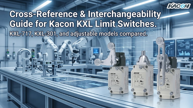
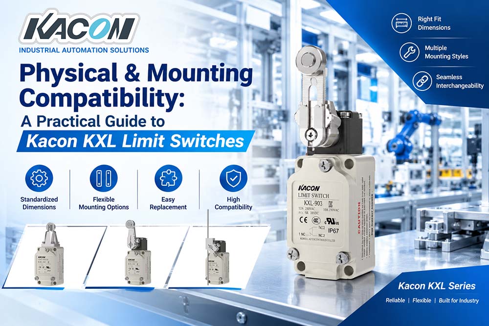
The Kacon KXL Series features a comprehensive range of actuators tailored to different mechanical movement profiles:
- Plungers & Roller Plungers: Ideal for short stroke, direct linear push movement.
- Roller Levers & Adjustable Levers: Suitable for rotary, cam-driven, or high-speed side-actuation applications.
- Flexible Spring Rods & Spring Wires: Designed for multi-directional actuation where travel directions are inconsistent.
The selected actuator must contact the moving mechanism at the proper angle and remain well within its specified operating force (OF), pre-travel (PT), and over-travel (OT) limits to prevent internal contact deformation or mechanical binding.

Practical Replacement Workflow
Follow this structured six-step engineering checklist when standardizing or replacing limit switches:
- Record Original Dimensions: Measure mounting hole centers, body length, lever offset, and conduit size.
- Identify Actuator Type: Determine if the motion requires a roller, plunger, or flexible rod contact.
- Compare Technical Drawings: Cross-reference original device blueprints with official Kacon industrial switch datasheets.
- Check Travel & Direction: Confirm operating angle, travel distance, and reset points match machine requirements.
- Confirm Electrical & Environmental Ratings: Verify voltage, contact configuration (NO/NC), and IP protection level per UL safety standards.
- Dry-Run Commissioning: Manually trigger complete machine movements before powering on full-scale production.
Quick Physical Compatibility Checklist
| Inspection Point | Verification Parameters |
|---|---|
| Mounting & Housing | Hole pattern, pitch distance, mounting orientation, and main body dimensions |
| Actuator Assembly | Actuator head type, lever arm length, roller diameter, and contact offset angle |
| Spatial Clearance | Body envelope clearance, actuator sweep radius, and cable gland bend radius |
| Kinematics & Motion | Operating force (OF), pre-travel (PT), overtravel (OT), and operating speed range |
| Wiring & Fasteners | Conduit thread type (M20/NPT/PG), mounting bolt size, and sealing gasket seats |
Conclusion
True physical compatibility relies on a complete synthesis of dimensions, mounting geometry, actuator kinematics, clearance, and travel characteristics. While Kacon KXL Series limit switches provide versatile options for retrofitting and standardization, final selection should always be verified against official engineering drawings and real-world operational machine tolerances.