
1. Real-World Client Case Study: Correcting an Installation Failure on a Conveyor Line
A prominent packaging system integrator in North America recently automated a heavy-duty box-sorting conveyor line. During the initial commissioning phase, the maintenance team noticed that several limit switches installed along the diversion gates were failing prematurely—some within just a few weeks of operation.
The Installation Mistakes
Upon inspection by a senior applications engineer, two critical installation errors were discovered:
- Improper Actuator Approach Angle: Technicians had mounted the roller-lever limit switches so that moving metal carton brackets struck the lever at a brutal 90-degree side angle instead of sliding smoothly across the roller arc. This excessive shear force snapped the actuator arms.
- Cable Ingress Failure: Control cables were fed into the switch housing from the top without a drip loop or proper cable gland, allowing cutting fluid and condensation to trickle directly down the wire into the electrical terminal block.
The Corrected Installation Solution
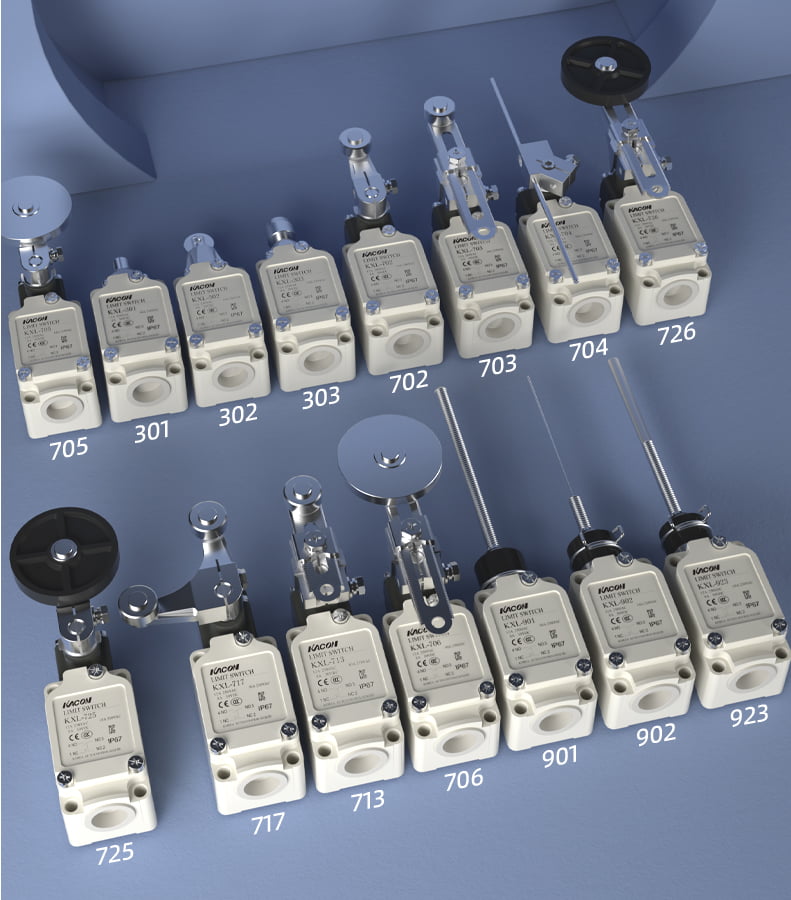
The integrator overhauled the mounting process by partnering with Kacon. They replaced the damaged units with heavy-duty Kacon KXL aluminum die-cast limit switches featuring an IP67 protection rating. They adjusted actuator cam angles to ensure smooth physical contact and installed downward-facing cable glands with drip loops to seal out moisture completely.
The corrected installation eliminated premature wear, securing millions of trouble-free operational cycles.
2. Step-by-Step Guide: How to Install a Limit Switch Properly
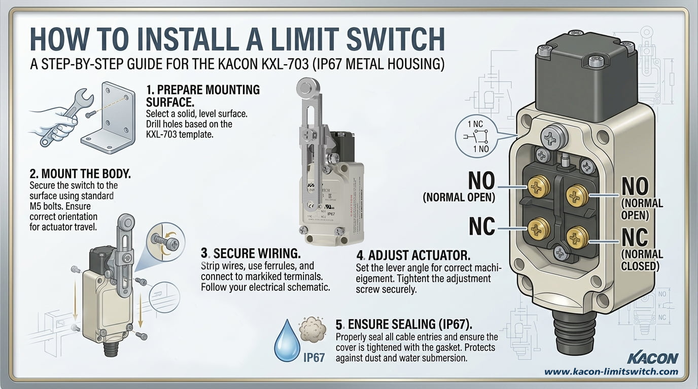
To ensure long-term mechanical reliability and precise electrical signaling, follow these five essential steps when installing an industrial limit switch:
Step 1: Lock Out / Tag Out (LOTO) and Mechanical Prep
Before mounting any hardware, ensure that the machine’s main electrical and pneumatic supplies are completely isolated following OSHA Control of Hazardous Energy (LOTO) Standards. Secure the mounting surface, ensuring it is flat, rigid, and free of heavy vibration that could loosen hardware over time.
Step 2: Position and Align the Actuator Correctly
The physical target (cam, dog, or machine slide) must engage the switch actuator smoothly without structural binding:
- Avoid Side-Loading: Never allow fast-moving parts to slam directly into the side of a plunger or lever at harsh angles. Maintain approach angles within manufacturer tolerances.
- Respect Travel Limits: Ensure the moving target depresses the lever within the specified operating travel range—allowing sufficient overtravel for machine safety, but stopping short of bottoming out or crushing the internal spring mechanism.
Step 3: Secure the Housing and Environmental Sealing
Bolt the switch firmly using thread-locking fluid or lock washers to prevent vibration loosening.
- Cable Glands Matter: Always use a rated cable gland (such as NPT, PG, or Metric threaded fittings matching your housing entry) to seal the wire entry point according to IEC Ingress Protection Standards or NEMA Enclosure Guidelines.
- Drip Loops: Form a small downward “drip loop” in the control cable immediately before entering the gland so that moisture, oil, or washdown fluids drop away naturally rather than tracking into the switch housing.
Step 4: Wire the Terminals Correctly
Open the internal housing cover and wire the terminal block according to your control system logic:
- For Safety Loops & E-Stops: Connect strictly to COM (Common) and NC (Normally Closed) terminals to maintain a fail-safe closed loop that opens upon target arrival or wire breakage. Safety circuit designs should align with ISO 13849-1 Machine Safety Standards.
- For Sequence Signals: Connect to COM and NO (Normally Open) terminals for momentary PLC triggering.
- Pro Tip: For low-voltage PLC micro-load loops (24V DC at under 10 mA), specify oxidation-resistant hardware like Kacon ZXG or KXM switches featuring 24K gold-plated contacts to prevent signal dropouts.
Step 5: Test Continuity and Commissioning
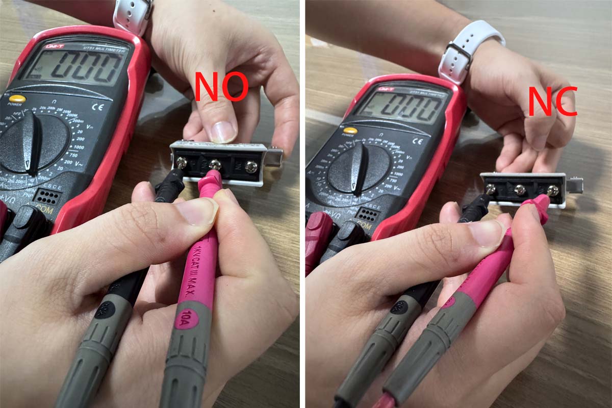
Before restoring main system power, verify wiring continuity with a digital multimeter following Fluke Continuity Testing Procedures. Manually actuate the switch arm and confirm zero-ohm continuity on closed contacts and infinite resistance (O.L) on open contacts.
3. Limit Switch Installation Best Practices Matrix
Reference this engineering summary table when installing limit switches across industrial equipment:
| Installation Phase | Potential Risk / Error | Correct Best Practice | Why It Matters |
|---|---|---|---|
| Mechanical Mounting | Side-impact forces or improper cam approach angles. | Ensure smooth rolling/sliding contact within recommended travel limits. | Prevents arm fracture, spring fatigue, and mechanical jamming. |
| Enclosure Wiring | Top-entering cable entry allowing fluid to pool and ingress. | Use bottom cable entry, IP-rated glands, and a drip loop. | Maintains IP67 rating, preventing short circuits and contact corrosion. |
| Electrical Hookup | Wiring safety interlocks into Normally Open (NO) terminals. | Wire safety loops strictly to Normally Closed (NC) terminals. | Ensures fail-safe machine shutoff if control wires break or disconnect. |
| Component Selection | Using silver contacts in low-voltage PLC input loops. | Specify Kacon 24K Gold-Plated Contacts for 24V micro-loads. | Prevents contact oxidation buildup and false “open loop” fault codes. |
Conclusion: Precision Installation Equals Maximum Uptime
Knowing how to install a limit switch properly goes far beyond bolting a housing to a frame and tightening terminal screws. By prioritizing correct mechanical alignment, applying proper environmental sealing techniques, and selecting rugged hardware like Kacon industrial limit switches, control engineers can guarantee operational safety and maximize plant productivity.
External Technical References & Standards
For detailed standards and engineering guidelines regarding electrical safety, enclosure ratings, and installation practices, consult these industry resources:
- OSHA Control of Hazardous Energy (Lockout/Tagout) Standards
- ISO 13849-1 Machine Safety Guidelines for Control Systems
- IEC International Electrotechnical Commission Guidelines
- NEMA 250 Enclosure Standards for Electrical Equipment
- Fluke Technical Resource: Testing Electrical Continuity with Multimeters