
In high-speed production lines and heavy industrial automation, unexpected downtime is a costly nightmare. A single false signal or minor contact failure from a standard industrial limit switch can halt an entire conveyor system, causing thousands of dollars in losses per hour.
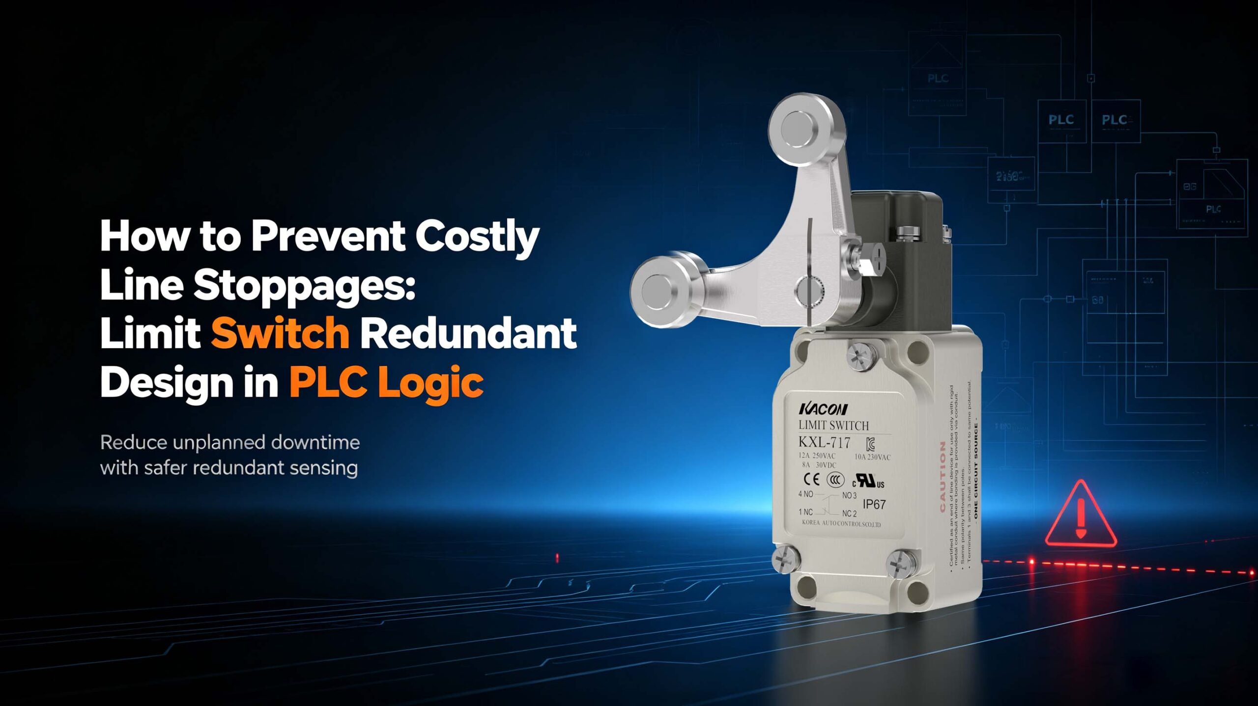
To eliminate these expensive false shutdowns, smart electrical engineers don’t just rely on higher-quality components—they implement a highly reliable PLC Redundant Design. By implementing a parallel circuit design combined with intelligent PLC logic detection, you can keep your production line running safely even if a limit switch physically fails.
1. Hardware Selection: Built for High-Frequency Industrial Survival
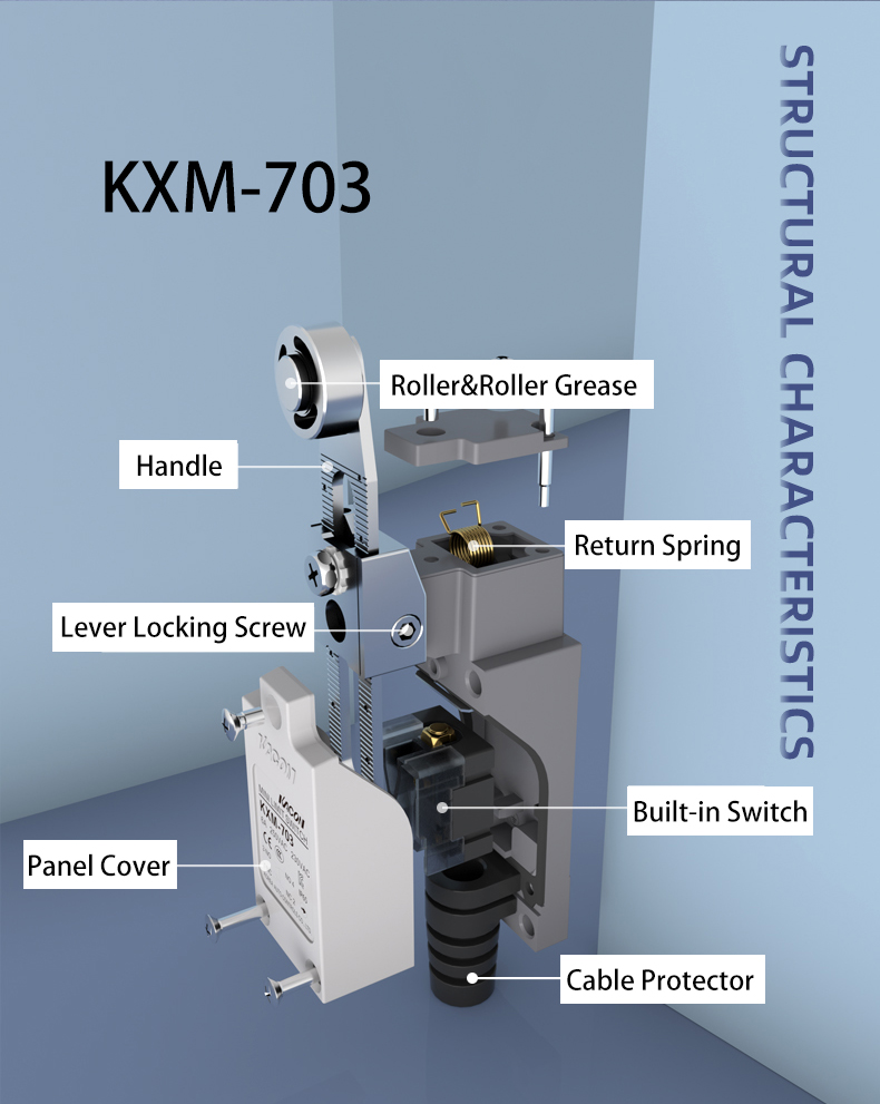
Redundancy only works if the individual components are built to last. For a parallel logic system that handles constant, high-frequency triggers, your industrial limit switches must meet strict mechanical and environmental standards.
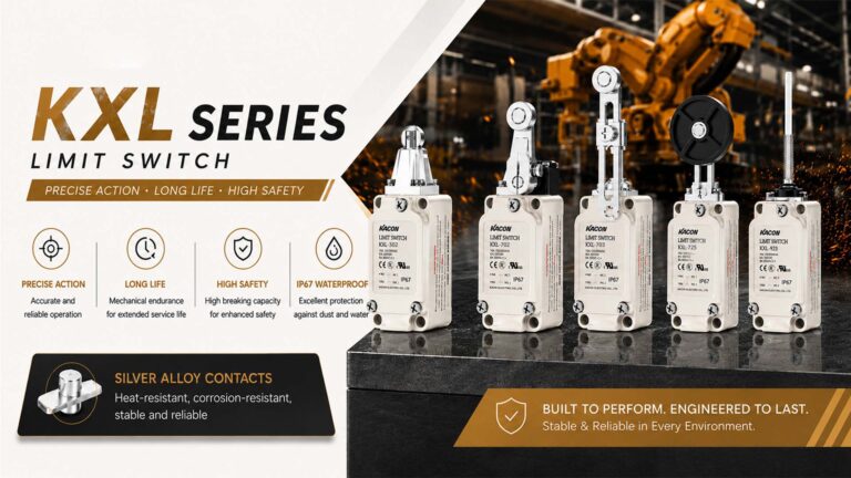
- Gold-Plated Contacts Technology: Standard copper or silver contacts suffer from micro-arcing and oxidation over time. For logic-level PLC inputs and low-current signals, you should choose limit switches engineered with premium gold-plated contact technology. Gold offers exceptionally low contact resistance and maximum anti-interference performance.
- Extended Lifespan for High Frequency: High-frequency applications demand heavy-duty durability. Ensure your selected switches have a mechanical lifespan of 1,000,000 times cycles and an electrical lifespan of 500,000 times cycles to withstand harsh factory floors.
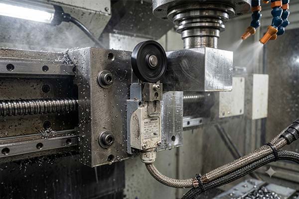
- IP67 Environmental Sealing Protection: Dust, oil, and cutting fluids are deadly to electrical contacts. An IP67 or higher ingress protection rating keeps the internal contact chamber completely sealed, preventing oxidation and premature component failure.
2. Circuit Design: Eliminating Common-Cause Failures via Parallel Wiring
The core of this redundant solution relies on connecting two separate limit switches (S1 and S2) in a parallel circuit layout using their Normally Open (NO) contacts. However, true industrial redundancy requires total physical separation.
The Golden Rule: Independent Parallel Wiring
To properly guard against system failures, S1 and S2 must be wired to the controller completely independently. They must not share common terminals or ground blocks. Sharing a terminal introduces a single point of failure—if that shared terminal oxidizes or suffers a mechanical break, both switches will fail simultaneously. This is known in safety engineering as a Common-Cause Failure.
3. The “1-out-of-2” (1oo2) PLC Detection Logic Control
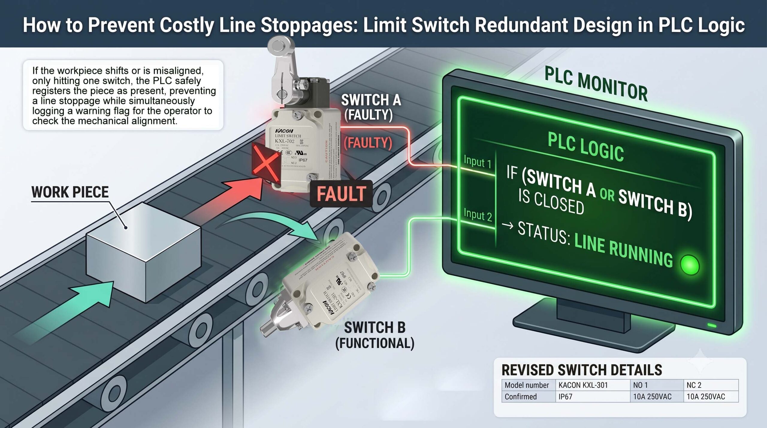
Once properly wired, the system relies on “1-out-of-2” (1oo2) voting logic processed in real-time by the PLC program. When a workpiece or machine arm moves into position, it physically hits both switches simultaneously.
The PLC interprets the incoming signals using specific operational logic to ensure maximum safety and uptime:
| Sensor S1 (Status) | Sensor S2 (Status) | PLC System Assessment | Action Taken |
|---|---|---|---|
| 0 (Open) | 0 (Open) | No workpiece present | Normal operation; continue line movement. |
| 1 (Closed) | 0 (Open) | Workpiece detected; Sensor S2 Failed | Keep Machine Running. Trigger minor warning light for maintenance. |
| 0 (Open) | 1 (Closed) | Workpiece detected; Sensor S1 Failed | Keep Machine Running. Trigger minor warning light for maintenance. |
| 1 (Closed) | 1 (Closed) | Workpiece detected; All systems normal | Normal operation; proceed to next step. |
If the workpiece shifts or is misaligned—only hitting one switch—the PLC safely registers the piece as present, preventing an expensive line stoppage while simultaneously logging a warning flag for the operator to check the mechanical alignment during scheduled breaks.
4. The Core Advantage: Seamless Fault Response & IEC Compliance
Why is this parallel PLC design so powerful? Let’s look at a real-world failure scenario:
Imagine a sudden electrical surge causes the contacts of S2 to suffer heavy arc erosion and fail completely. In a standard single-switch system, the production line drops dead instantly, leading to severe operational bottlenecks.
In this redundant setup, the PLC simply looks to S1. As long as S1 maintains a contact resistance of $\le 50\text{ m}\Omega$ (fully compliant with IEC 60947 standards), it will reliably transmit the signal. The machine continues its cycle without missing a single beat, allowing your maintenance team to replace the faulty S2 switch during a scheduled weekend break rather than forcing an emergency midnight shutdown.
Summary Checklist for Redundant Limit Switch Configurations
| Feature Component | Technical Requirement | Why It Matters for Industrial SEO |
|---|---|---|
| Contact Plating | Gold-Plated Contacts (K-Gold) | Prevents signal drop on low-current, logic-level PLC loops. |
| Circuit Topology | Parallel Wiring (NO Contacts) | Allows seamless “1-out-of-2” (1oo2) backup functionality. |
| Terminal Block | Strictly Independent Separation | Eliminates risky Common-Cause Failures entirely. |
| Electrical Rating | IEC 60947 Compliant ($\le 50\text{ m}\Omega$) | Guarantees loop signal integrity when one switch fails. |
5. Secure Your Factory Uptime: Professional Automation Support
Redundant PLC logic detection transforms simple physical limit switches into a highly intelligent safety net for heavy manufacturing. By upgrading to industrial-grade gold-plated switches and applying parallel independent wiring principles, you protect your facility from the massive financial hit of unexpected line stoppages.