
1. Real-World Case Study: Correcting a Safety Loop Wiring Error
A European automation system integrator designed high-precision sorting machines for electronic components. During initial field testing, the equipment experienced frequent, unexplained emergency stops and erratic Programmable Logic Controller (PLC) error codes.
The Wiring Mistake
Upon inspecting the control cabinets, the engineering team discovered that technicians had wired the safety interlock micro switches using the Normally Open (NO) terminals instead of the Normally Closed (NC) terminals:
- No Fail-Safe Protection: Because the safety interlock switches were wired as Normally Open, a broken signal wire, loose terminal screw, or severed cable appeared identical to a “safe” resting state (0V DC) to the PLC input card.
- Silent Failures: The safety circuit lacked fail-safe redundancy, creating a severe operational hazard where guard doors could open without triggering an emergency stop.
The Engineering Solution
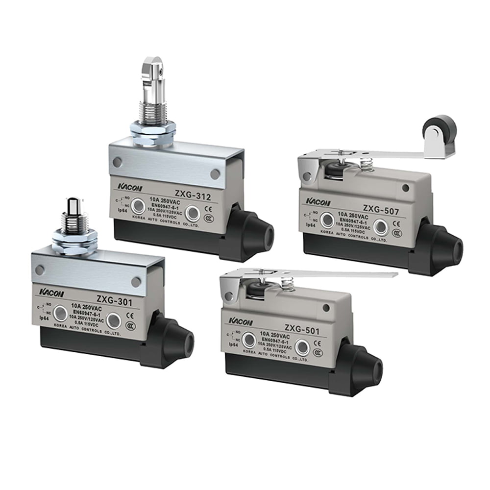
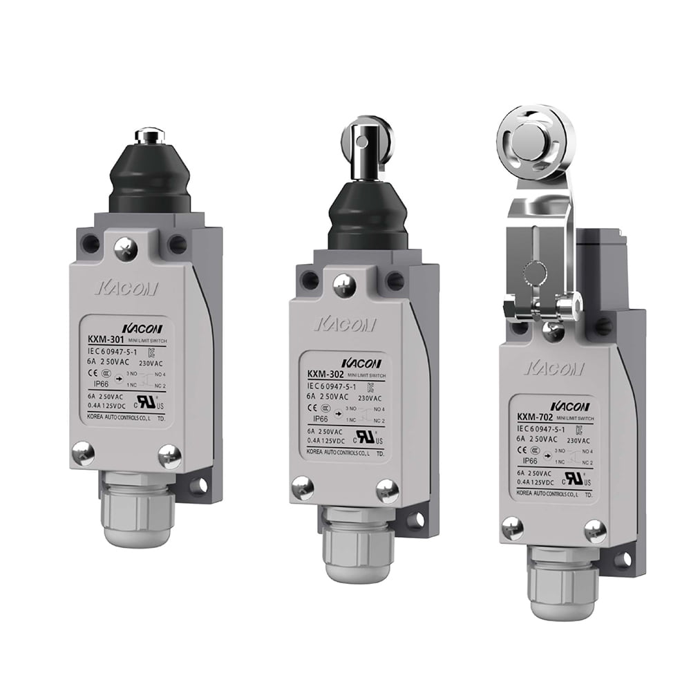
The engineering team re-wired the system into a fail-safe Normally Closed (NC) loop architecture. They upgraded to high-reliability industrial limit switches—specifically Kacon’s ZXG and KXM series—featuring dual-circuit (1NO + 1NC) contact blocks and oxidation-proof 24K gold-plated contacts.
This correction established continuous loop verification compliant with functional safety standards like ISO 13849-1 Machine Safety Guidelines and OSHA Machine Guarding Standards. The fail-safe loop eliminated false error codes and guaranteed immediate power cutoff if a signal wire ruptured.
2. Micro Switch Terminals Explained: COM, NC, and NO
Before connecting field wiring, you must correctly identify the three standard terminal pins found on snap-action micro switches and industrial limit switches according to IEC 60947-5-1 Switchgear Standards:
- COM (Common): The primary power feed or signal input terminal. Your incoming positive source conductor (typically 24V DC or 110V AC) connects here.
- NC (Normally Closed – Terminals 11/12): The internal circuit path remains closed (conducting electricity) until the switch actuator is physically depressed. Best for: Emergency stop loops, safety interlocks, overtravel limits, and fail-safe cut-offs.
- NO (Normally Open – Terminals 13/14): The internal circuit path remains open (non-conducting) until the actuator is physically depressed. Best for: Part detection, item counting, sequence start triggers, and process execution signals.
3. Step-by-Step Guide: How to Wire a Micro Switch to a PLC
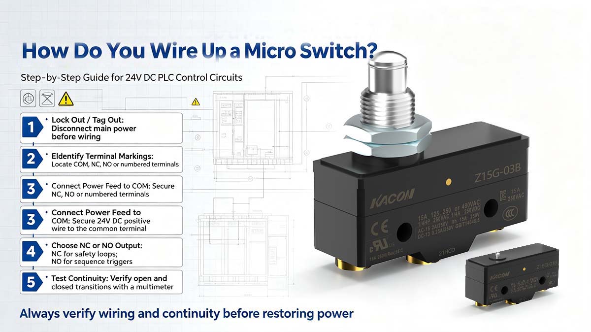
Follow these five standard industrial steps to safely wire a micro switch or limit switch into a 24V DC PLC digital input channel:
Step 1: Execute Lockout/Tagout (LOTO)
Disconnect and isolate all incoming power sources to the machinery electrical enclosure before handling wiring to prevent short circuits, equipment damage, or electrical shock.
Step 2: Identify Terminal Markings
Inspect the side or base of the switch body for terminal identifiers: COM, NC, NO, or standardized IEC contact numbers (11/12 for NC, 13/14 for NO).
Step 3: Connect Incoming Power to COM
Strip approximately 6mm of insulation from your 24V DC positive supply wire. Securely crimp an insulated ferrule or screw the bare wire directly into the COM (Common) terminal pin.
Step 4: Wire the Output Signal Terminal (NC vs. NO)
- For Safety Loops & Overtravel Limits: Connect a wire from the NC terminal to your PLC safety input or safety relay. This ensures that a cut wire or power loss automatically trips a safe system shutdown.
- For Sequence Triggers & Counters: Connect a wire from the NO terminal to your standard PLC digital input card module.
Step 5: Perform Multimeter Continuity Testing
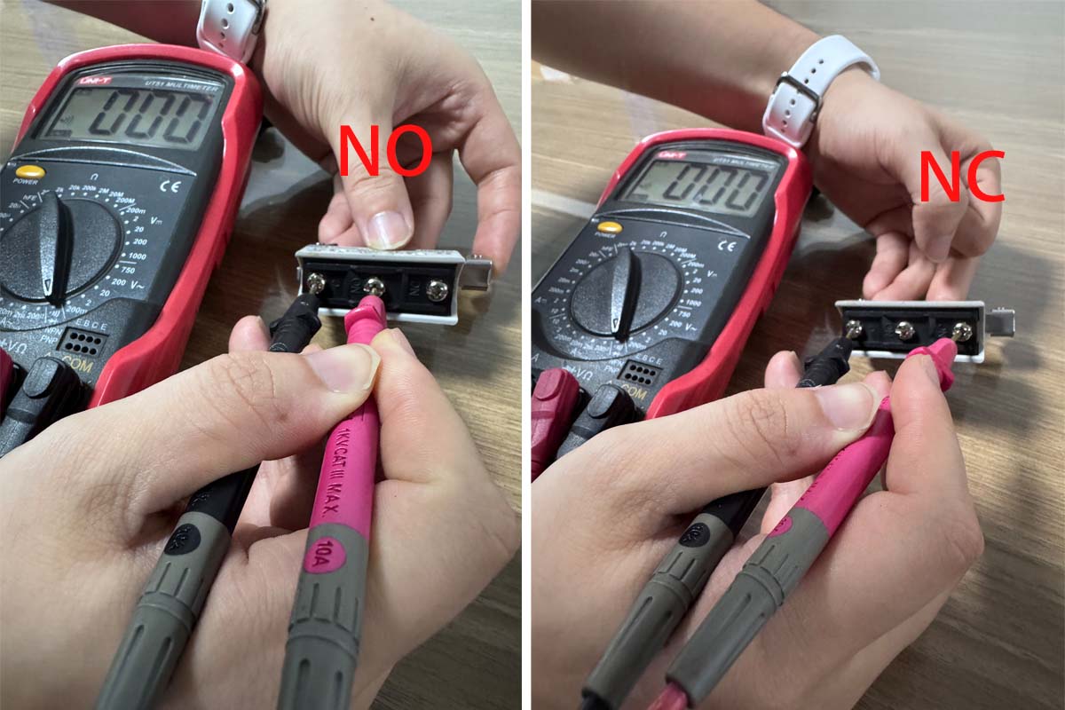
Before energizing the cabinet, set a digital multimeter to Continuity / Resistance mode. Manually depress the actuator lever to confirm crisp, immediate transitions between and infinite resistance (open). Refer to Fluke’s Continuity Testing Guide for detailed multimeter diagnostics.
4. Micro Switch Wiring Selection Matrix
Use this reference table to select the correct wiring setup and terminal logic based on your automation application requirements:
| Application Goal | Terminals Used | Circuit State at Rest | Circuit State Actuated | Key Engineering Advantage |
|---|---|---|---|---|
| Safety Interlock / E-Stop | COM to NC (Terminals 11/12) |
Closed (24V Signal) | Open (0V Signal) | Fail-Safe Protection: A severed wire or loose connection instantly trips a system shutdown. |
| Process Trigger / Object Counter | COM to NO (Terminals 13/14) |
Open (0V Signal) | Closed (24V Signal) | Discrete Signal Control: Sends a 24V voltage pulse to the PLC only when physical contact is made. |
| Micro-Load PLC Integration | COM to NC / NO | Stable Loop State | Stable Loop State | Oxidation Resistance: Pair with Kacon 24K gold-plated contacts to prevent high contact resistance. |
Summary: Designing Reliable Switch Circuits
Mastering how to wire a micro switch—by strategically matching COM, NC, and NO terminal configurations to your control logic—prevents costly downtime and ensures compliance with international machinery safety standards.
Combining correct fail-safe wiring practices with micro-load-optimized hardware, such as Kacon gold-contact industrial limit switches, delivers stable signal transmission and long-term operational reliability across automated production lines.
External Technical References & Standards
For further technical documentation regarding wiring practices, switch terminals, and functional safety standards, consult these authoritative industry resources:
- IEC 60947-5-1 Specifications for Low-Voltage Switchgear and Controlgear
- ISO 13849-1 Safety of Machinery – Safety-Related Parts of Control Systems
- OSHA General Industry Safety Standards – Machine Guarding Regulations
- Fluke Technical Guide: Testing Electrical Continuity with Digital Multimeters
- NEMA 250 Specification Standard for Electrical Equipment Enclosures