
Fortunately, identifying the contact configuration is straightforward once you understand standardized terminal numbering conventions, physical multimeter testing procedures, and contact schematic symbols.
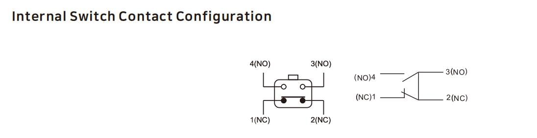
1. The Visual Method: Check Terminal Numbers and Schematics
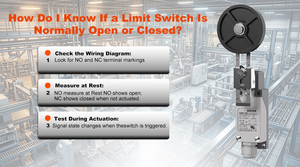
International industrial standards simplify contact identification directly at the terminal block. Under recognized control switchgear guidelines—such as IEC 60947-5-1 Low-Voltage Control Standards—industrial limit switches follow strict terminal numbering rules:
- Normally Closed (NC) Terminals end in 1 and 2:
- Examples: Terminals labeled 11 and 12 (or 21 and 22 for second-pole circuits) designate an NC contact block.
- Normally Open (NO) Terminals end in 3 and 4:
- Examples: Terminals labeled 13 and 14 (or 23 and 24 for second-pole circuits) designate an NO contact block.
In addition, high-reliability switches feature a laser-engraved circuit schematic on the exterior housing:
- NC Schematic Symbol: Displays a solid contact bridge resting physically against the terminal nodes, representing a completed electrical path.
- NO Schematic Symbol: Displays a contact bridge hovering above or detached from the terminal nodes, representing an open electrical path.
When selecting enclosures for outdoor or washdown environments, verify that the housing complies with recognized ingress metrics like NEMA Enclosure Standards or IEC Ingress Protection Ratings to protect internal contact labels from fading or environmental degradation.
2. The Testing Method: Using a Digital Multimeter (Continuity Test)
If terminal markings are obscured or worn off an old switch, the definitive method to determine contact state is an electrical continuity test using a digital multimeter.
Ensure the machine is fully de-energized. Disconnect field wires from the limit switch terminals to prevent parallel resistance paths from back-feeding through PLC input cards. Always adhere to OSHA Hazardous Energy Control (LOTO) Regulations.
Turn your multimeter dial to Continuity Mode (symbolized by a soundwave or diode icon) or the lowest Resistance ($\Omega$) range. Touch probe tips together to verify zero lead resistance before testing.
Place meter probes across a pair of terminals while the switch actuator sits in its default resting state:
- Continuous Tone : Electricity flows freely. The circuit is closed at rest. This is a Normally Closed (NC) contact block.
- Silent Meter: No current flows. The circuit is open at rest. This is a Normally Open (NO) contact block.
Manually compress the limit switch roller, plunger, or wobble stick while maintaining probe contact across the terminals:
- The meter state must invert instantly—a continuous tone on an NC contact silences immediately to O.L, while an open NO contact completes the circuit, generating a steady tone.
For additional testing reference guidelines, consult Fluke’s Guide on How to Test for Continuity.
3. Contact Resistance Diagnostics: Why Resistance Fluctuates
When testing a Normally Closed (NC) contact, your multimeter should ideally display near-zero resistance (under 0.5 $\Omega$). If the reading fluctuates wildly between 20 $\Omega$ and several hundred ohms, the switch is suffering from surface oxidation or contact pitting.
The Cause: Micro-Loads and Oxide Layer Buildup
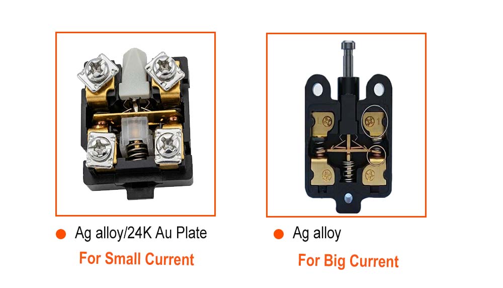
Modern PLCs operate on micro-load levels (typically 24V DC at under 10 mA). Standard silver-alloy contacts require higher currents to produce a micro-arc that burns off tarnish. On low-power circuits, silver forms an insulating oxide film, causing the PLC to interpret a mechanically closed switch as an open circuit.
The Solution: Kacon Dual-Circuit Gold Contact Switches
Specifying high-grade industrial hardware—such as the Kacon ZXG and KXM Series—eliminates contact logic ambiguity and micro-load signal failures:
- Standard 1 N/O + 1 N/C Dual-Circuit Architecture: Kacon switches feature independent NO and NC contact blocks within a single housing, allowing field technicians to select the exact circuit required without ordering separate switch bodies.
- 24K Gold-Plated Contacts (Ag Alloy / 24K Au Plate): Because gold is chemically inert, it prevents oxidation entirely. Gold-plated contacts maintain ultra-low contact resistance ($\le$ 25 $\text{m}\Omega$ to 50 $\text{m}\Omega$), ensuring uninterrupted signal transmission to low-voltage PLCs.
All safety-critical limit switches should incorporate positive opening mechanisms engineered in accordance with ISO 13849-1 Functional Safety Guidelines to guarantee forced disconnection during fault conditions.
4. Quick Identification & Testing Reference Matrix
Maintenance personnel can utilize this reference matrix to identify and test limit switch contacts on the factory floor:
| Terminal Markings | Schematic Symbol | Multimeter (Switch at Rest) | Multimeter (Switch Actuated) | Contact Type | Primary Application |
|---|---|---|---|---|---|
| 11 / 12 | Bridge touching nodes | BEEPS | SILENT | Normally Closed (NC) | Safety interlocks, E-Stops, overtravel limits |
| 13 / 14 | Bridge detached above nodes | SILENT | BEEPS | Normally Open (NO) | Part presence counting, sequence triggering |
| Fluctuating Ohms | Any | Erratic resistance reading | Erratic resistance reading | Oxidized / Failing | Replace with Kacon Gold-Plated Contacts |
Conclusion: Testing with Confidence
Determining whether a limit switch is normally open or closed is fundamental to safe control system wiring. By inspecting standardized terminal numbers (11/12 for NC and 13/14 for NO) and verifying electrical state transitions using a multimeter continuity test, electrical personnel can configure machine control circuits accurately.
To keep control loops operating reliably over millions of cycles, equip production machinery with dual-circuit, gold-contact limit switches from Kacon—ensuring that closed circuits maintain true zero-resistance connections every time.
External Technical References & Standards
For further reading on industrial wiring standards, testing methodologies, and machine safety compliance, explore the following resources:
- IEC 60947-5-1 Standard for Control Circuit Devices & Switching Elements
- ISO 13849-1 Safety of Machinery – Safety-Related Parts of Control Systems
- Fluke Official Application Guide: How to Test for Electrical Continuity
- OSHA Standard 1910.147 – Control of Hazardous Energy (Lockout/Tagout)
- NEMA 250 Enclosures for Electrical Equipment Specification
- IEC Ingress Protection (IP) Rating System Summary