
Real-World Client Case Study: The Danger of Incorrect Contact Logic
A major automotive stamping facility in North America recently integrated a high-speed robotic transfer press. During the final commissioning phase, safety auditors noticed an alarming vulnerability in the emergency stop control loop.
The Wiring Mistake
The electrical contractors had wired the safety interlock limit switches using their Normally Open (NO) contacts instead of Normally Closed (NC) circuits.
- The Hazard: Because an NO circuit is open by default when the machine is at rest, a severed control wire, a loose terminal block, or a broken sensor cable would look identical to a “safe” resting state to the Programmable Logic Controller (PLC).
- The Consequence: If a forklift had snagged the cable during production, the controller would never have detected the break, disabling the emergency stop function and creating a severe hazard for operators.
The Corrected Solution
The plant engineering team immediately overhauled the control panels, rewiring every safety interlock to Normally Closed (NC) fail-safe loops using heavy-duty industrial hardware from Kacon. By implementing proper dual-circuit architecture (1 N/O + 1 N/C) and utilizing gold-plated contacts to prevent micro-load oxidation, the facility achieved absolute compliance with global safety standards and eliminated control ambiguity entirely.
1. The Default State: Normally Open (NO) vs. Normally Closed (NC)
An industrial limit switch contains internal contact blocks engineered for distinct operational roles. To understand whether your switch should be open or closed, you must first define its state when no external force acts upon it. This is called the “Normal” or “Resting” state.
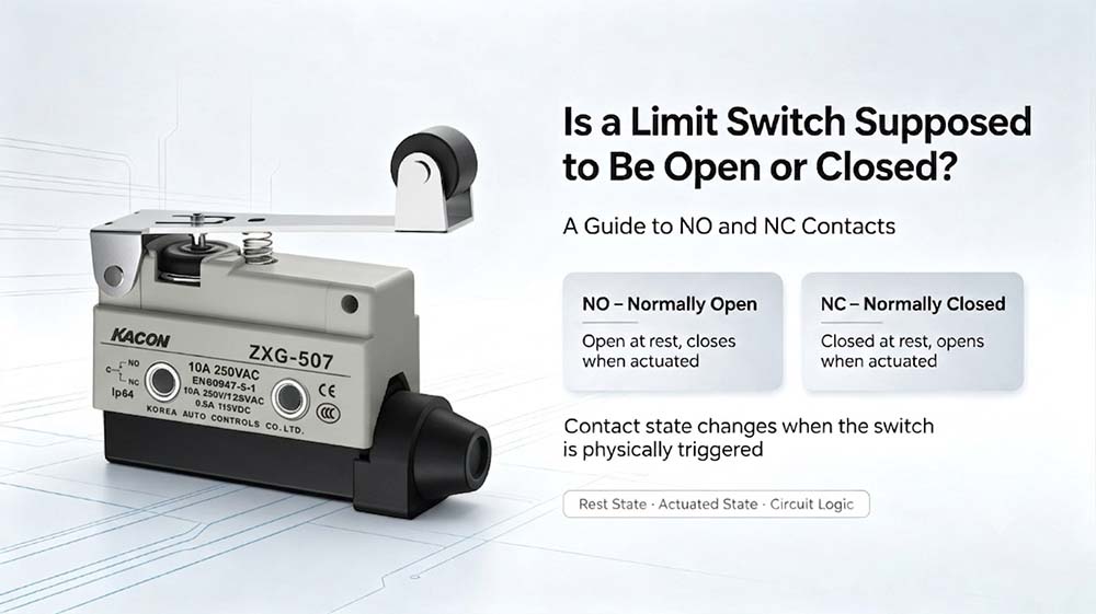
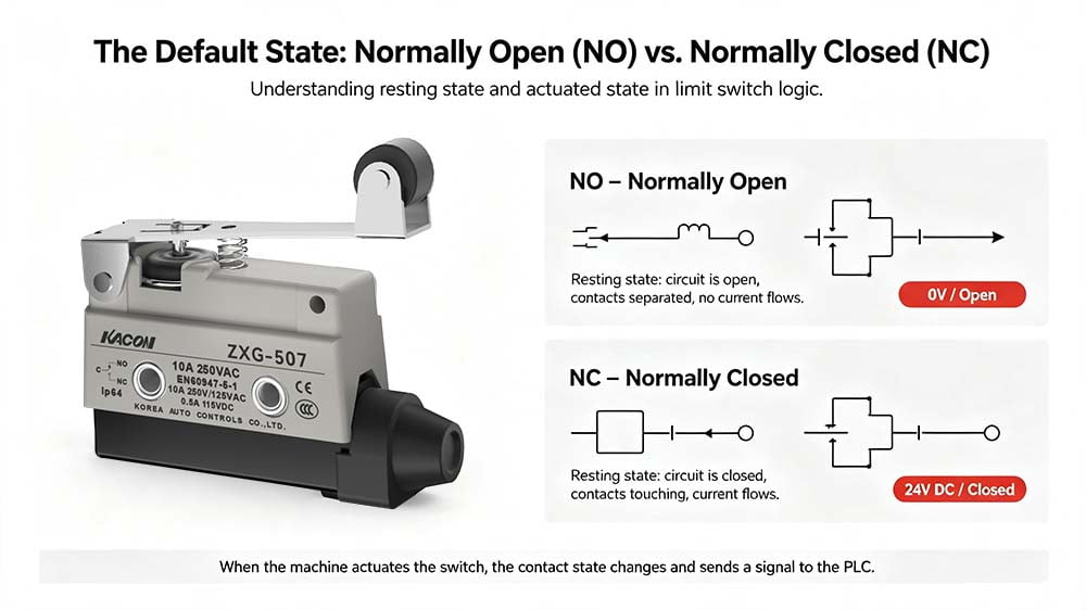
- Normally Open (NO / Form A) Contacts: In the resting state, this circuit is open (non-conducting, 0V). The metal contacts are physically separated. When an actuator physically strikes the switch mechanism, the contacts snap together and become closed, sending a voltage signal (24V DC) to the PLC.
- Normally Closed (NC / Form B) Contacts: In the resting state, this circuit is closed (conducting, 24V DC). The metal contacts are touching, allowing electricity to flow freely. When the machine hits the switch, the contacts are forced apart, opening the circuit and cutting the signal.
Wiring standards for control switchgear are codified in international specifications such as IEC 60947-5-1 Low-Voltage Switchgear Directives.
2. When Should the Switch Be CLOSED? (The Fail-Safe Safety Loop)
In industrial automation, safety circuits must almost always be wired as Normally Closed (NC). This means that during normal, safe machine operation, the limit switch contact remains closed, allowing electrical current to flow to the main safety relay or safety PLC input card.
Why Use a Closed Circuit for Safety?
This principle is known as fail-safe design. When a safety circuit is wired as Normally Closed, the PLC expects a continuous 24V DC signal to confirm that protective guards are closed and overtravel limits are clear.
If a cable is severed, a wire pulls loose, or power drops, the continuous signal is broken (the circuit becomes open). The controller immediately detects the loss of signal and shuts down the machine safely, satisfying strict functional safety criteria under ISO 13849-1 Machine Safety Guidelines.
If an installer incorrectly uses a Normally Open (NO) contact for safety, a broken cable would look identical to an unactuated, “safe” condition. The machine would continue running without a functional emergency stop mechanism.
Engineers can review IEEE Educational Resources for Control Systems to explore theoretical fundamentals on fail-safe relay logic design.
3. When Should the Switch Be OPEN? (Sequential Triggers)
Limit switch contacts are wired as Normally Open (NO) when their primary purpose is to trigger an action upon part arrival rather than interrupt power during an emergency.
For example, consider a conveyor positioning loop:
The NO limit switch contact sits in its default Open state. No current flows to the PLC digital input card.
A pallet travels down the line and contacts the roller lever actuator of the limit switch.
The switch snap-action mechanism closes the NO contacts instantly, completing the 24V DC circuit.
The momentary Closed signal alerts the PLC: “Part in position—engage pneumatic clamp.”
As the part moves past the station, internal return springs reset the switch contacts back to the default Open state.
4. The Micro-Load Problem: When “Closed” Fails to Conduct
There is a critical hidden fault condition in automation circuits involving Normally Closed contacts.
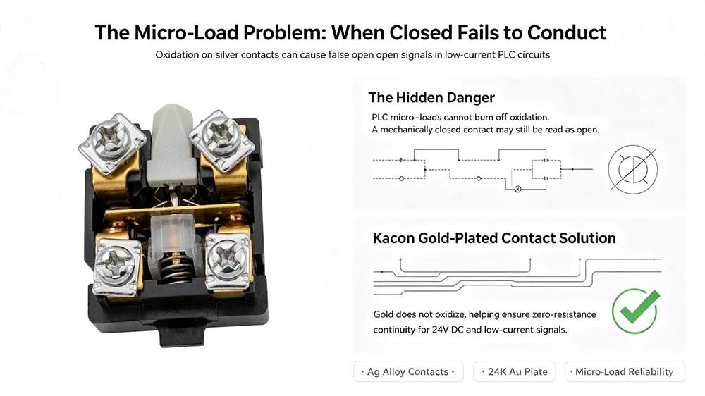
For a Normally Closed circuit to guarantee safety, it must conduct current cleanly. Modern PLCs use low-voltage input channels (typically 24V DC drawing under 10 mA). These micro-load currents lack the electrical energy required to burn off natural oxidation on standard silver contact surfaces.
Over time, an insulating oxide layer forms on silver contacts. The contact bridge may close mechanically, but the electrical signal is blocked by the tarnish film. The PLC interprets this high-resistance state as an open circuit, triggering false safety trips and intermittent downtime.
The Kacon 24K Gold Contact Solution
To eliminate micro-load signal failures, precision limit switches from Kacon—such as the ZXG and KXM Series—utilize Ag alloy / 24K Au-plated contacts on dual-circuit (1 N/O + 1 N/C) architectures.
According to technical datasheets, Kacon limit switches maintain strict initial contact resistance limits:
- ZXG Series: Max 50 $\text{m}\Omega$ contact resistance (Ag alloy / 24K Au Plate, IP65 polymer housing)
- KXM Series: Max 25 $\text{m}\Omega$ contact resistance (Ag alloy / 24K Au Plate, IP66 compact housing)
- KXL Series: Max 15 $\text{m}\Omega$ contact resistance (Heavy-duty aluminum die-casting, IP67 enclosure)
Because gold is chemically non-reactive, it resists oxidation entirely. When a Kacon safety switch rests in its Normally Closed position, it maintains low milliohm resistance for low-voltage PLC signals.
Ensuring that switch housings comply with recognized ingress protection classifications—such as those defined by NEMA Enclosure Standards and the IEC IP Code System—prevents coolant or dust ingress from compromising internal contacts.
5. Contact State Reference Matrix
To assist field technicians in diagnosing limit switch logic, refer to this quick operational matrix:
| Contact Type | State When Machine is SAFE / AT REST | State When Machine ACTUATES Switch | Primary Application | Kacon Hardware Feature |
|---|---|---|---|---|
| Normally Closed (NC) | CLOSED (Signal 24V ON) | OPEN (Signal 0V OFF) | Emergency stops, safety interlocks, overtravel limits | Positive Opening Mechanism mechanically shears welded contacts open under fault conditions. |
| Normally Open (NO) | OPEN (Signal 0V OFF) | CLOSED (Signal 24V ON) | Sequential process triggers, part counting, cycle indexing | 24K Gold-Plated Contacts eliminate contact bounce and oxide buildup on micro-loads. |
Conclusion: Flexibility and Reliability in Control Logic
So, is a limit switch supposed to be open or closed? A well-designed industrial control loop utilizes both states simultaneously.
It relies on the Closed (NC) state to monitor safety interlocks and wire continuity, and it uses the Open (NO) state to receive sequential machine commands. By selecting industrial-grade limit switches like those from Kacon—offering dual-circuit 1 N/O + 1 N/C configurations with gold-plated contacts—automation engineers ensure reliable logic execution, workforce safety, and maximum plant uptime.