
1. The Short Answer for Limit Switch: What Ohms Should You See?
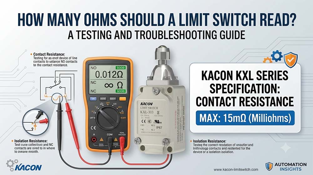
When testing a standard electromechanical limit switch with a digital multimeter set to the Resistance (mΩ) or Continuity mode, you will encounter two primary electrical states:
- When the Switch is Closed (Conducting State): You should see near-zero resistance—typically less than 0.1 to 0.5 Ohms on standard field meters, or strictly beneath the manufacturer’s maximum initial contact resistance specification. A steady continuity tone confirms a complete electrical path.
- When the Switch is Open (Non-Conducting State): You should see O.L (Over Limit / Open Loop) or Infinity. This indicates absolute electrical isolation between the contacts.
If your multimeter displays fluctuating numbers, elevated resistance (e.g., several ohms to hundreds of ohms), or fails to transition cleanly between zero and infinity, the switch suffers from contact pitting, mechanical wear, or surface oxidation.
2. Kacon Limit Switch Contact Resistance Specifications
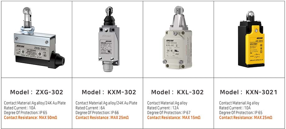
To ensure precision signal transmission and minimal voltage drop across industrial control loops, limit switch models feature distinct contact geometries, materials, and maximum initial contact resistance limits.
Compliance with low-voltage switchgear testing guidelines—such as IEC 60947-5-1 Specifications for Control Circuit Devices—ensures that initial contact resistance remains strictly controlled across production lots.
Below are the maximum initial contact resistance specifications for Kacon’s primary industrial limit switch series:
| Model Series | Contact Form | Contact Material | Max Initial Contact Resistance | Housing Material & Protection Rating |
|---|---|---|---|---|
| ZXG | 1 N/O + 1 N/C | Ag alloy / 24K Au Plate | MAX 50mΩ | Plastic Housing (IP65) |
| KXM | 1 N/O + 1 N/C | Ag alloy / 24K Au Plate | MAX 25mΩ | Plastic Housing (IP66) |
| KXL | 1 N/O + 1 N/C | Ag alloy | MAX 15mΩ | Aluminum Die-Casting (IP67) |
| ELN | 1 N/O + 1 N/C | Ag alloy | MAX 50mΩ | Aluminum Die-Casting (IP65 / IP68) |
| KXN | Multi-circuit options (1 N/O + 1 N/C, 2 N/C, etc.) | Ag alloy | MAX 25mΩ | Plastic Housing (IP65) |
Engineering Insight: Models like the ZXG and KXM Series incorporate 24K gold-plated contacts. Gold prevents surface oxidation, allowing the switch to maintain ultra-low contact resistance even when interfacing with low-power PLC digital input channels.
3. Step-by-Step Guide: How to Measure Limit Switch Resistance
To obtain accurate ohm readings and prevent false diagnostics when checking a limit switch on-site, follow this standardized procedure:
Never attempt to measure resistance on an energized circuit. Disconnect main power to the machinery and verify zero voltage state to prevent damage to your meter or electrical shock, maintaining strict alignment with OSHA Hazardous Energy Control (LOTO) Directives.
Disconnect at least one field wire from the switch terminal block. Testing resistance while the switch remains wired into a PLC input card or safety relay allows parallel circuit paths to skew your resistance reading.
Turn the digital multimeter dial to the Resistance mode. Short your meter probes together to confirm lead resistance. Subtract this baseline lead offset from your eventual terminal measurement.
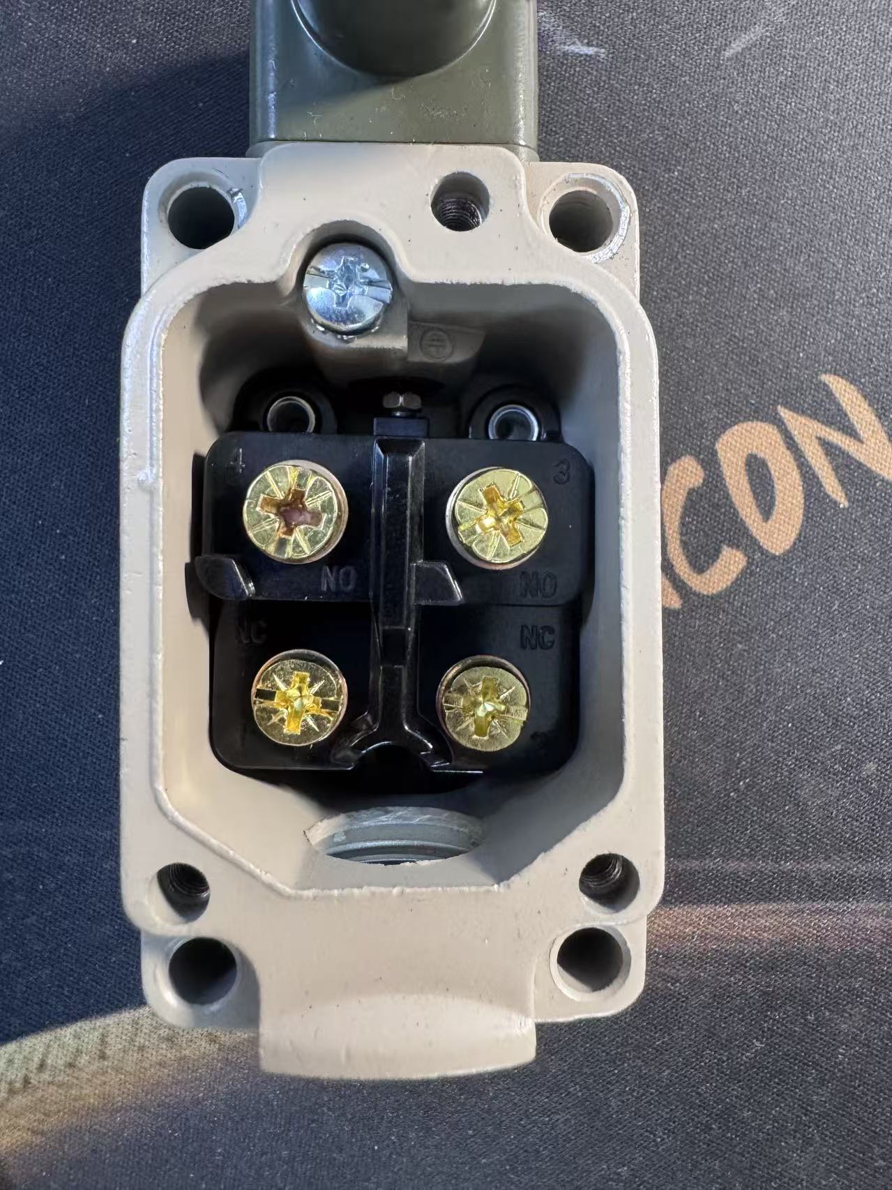
Place meter probes across the COM (Common) and NC (Normally Closed) terminals while the switch is at rest (unactuated).
- At Rest: Expected reading is near resistance (strictly below the manufacturer’s maximum rating, e.g., max 15 mΩ to 50 mΩ).
- Actuated: Manually compress the switch lever. The meter must instantly jump to O.L (Infinity).
Place meter probes across the COM and NO (Normally Open) terminals while the switch is at rest.
- At Rest: Expected reading is O.L (Infinity).
- Actuated: Manually compress the switch lever. Resistance must drop immediately to near value.
4. Troubleshooting High Resistance: The “False Open” Fault
What happens if a multimeter shows that a limit switch is mechanically actuated, but the closed-contact resistance reads several hundred ohms instead of near-zero? The PLC will fail to register a HIGH signal, throwing intermittent fault codes.
The Root Cause: Contact Oxidation in Micro-Load Circuits
Modern PLCs operate on low energy levels (typically 24V DC at under 10 mA). Standard silver-alloy contacts require higher electrical currents to produce a micro-arc that burns off natural oxidation.
When silver contacts are subjected exclusively to micro-load PLC inputs, a thin, non-conductive oxide layer accumulates over time. This layer acts as a resistor, raising the contact resistance to dozens or hundreds of ohms. The switch clicks mechanically, but the signal is blocked electrically.
The Solution: Gold-Plated Contact Technology
To eliminate high-resistance signal faults, specify switches engineered for low-current reliability. Switches like the Kacon ZXG and KXM Series feature Ag alloy / 24K gold-plated contacts.
Because gold is chemically inert, it does not form oxide films. This guarantees that contact resistance stays within specified milliohm limits across millions of low-current switching operations.
When selecting limit switches for harsh washdown or high-dust environments, ensure the housing meets applicable sealing standards such as NEMA Enclosure Standards or IEC Ingress Protection Ratings to prevent external moisture from corroding internal terminals.
Conclusion: Accurate Resistance Readings Guarantee Uptime
To summarize: a healthy closed limit switch contact should read near-zero ohms (adhering strictly to manufacturer thresholds like Kacon’s 15 mΩ to 50 mΩ), while an open contact must read infinite resistance (O.L).
By mastering resistance diagnostic procedures and specifying high-reliability hardware—such as Kacon’s gold-contact limit switches—maintenance teams can rapidly resolve intermittent signal drops, optimize machinery safety loops, and maximize production uptime.