
1. The Visual Method: Checking the Mechanical Actuator
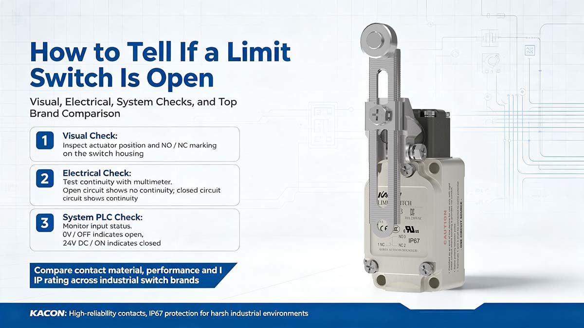
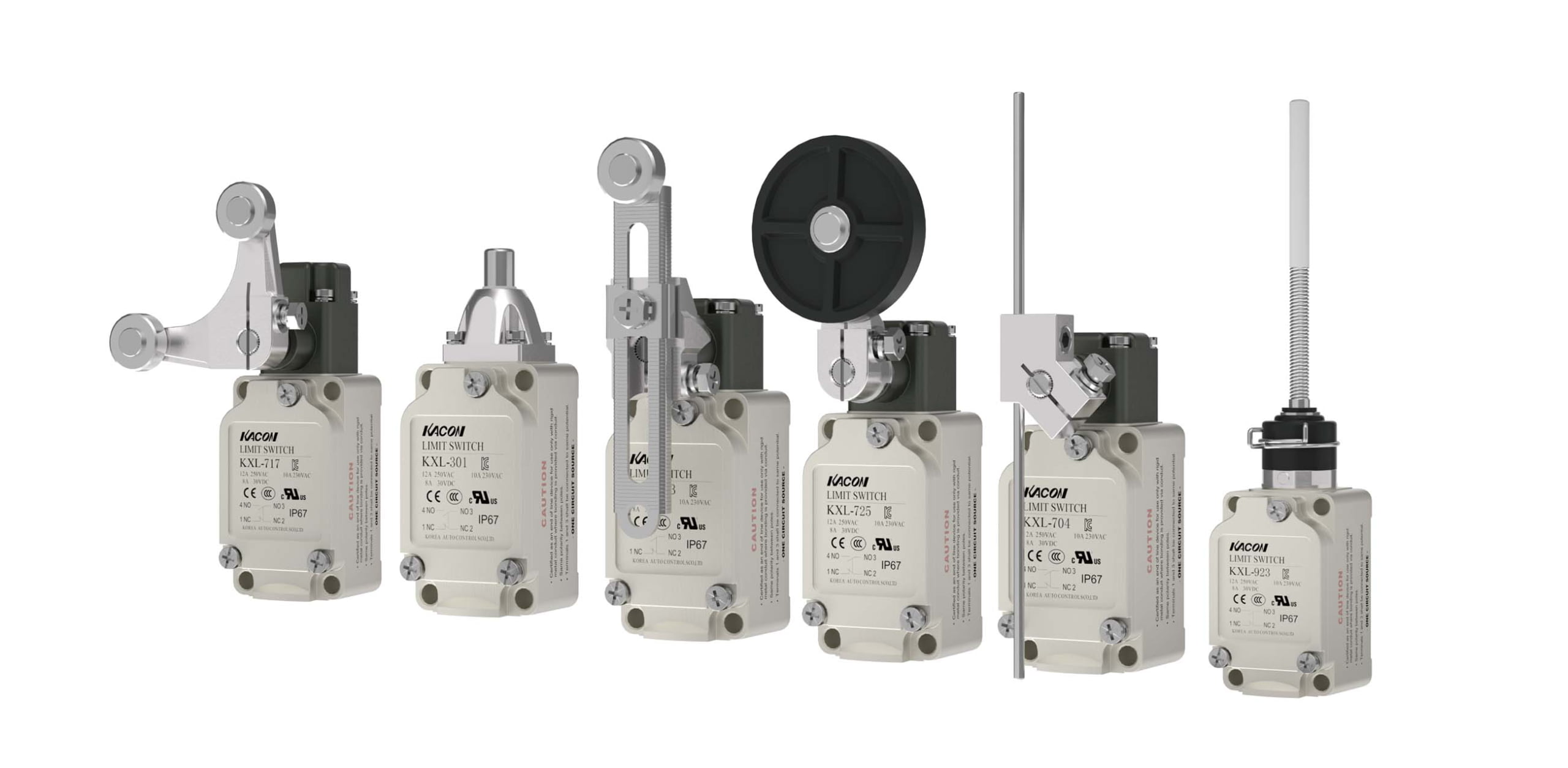
Before reaching for electrical tools, a quick physical inspection can often tell you if a limit switch is in an open state. However, to read the visual clues correctly, you must first know whether the switch was wired using Normally Open (NO) or Normally Closed (NC) contacts.
- If wired as Normally Closed (NC): The switch is open only when the machine physically contacts and depresses the actuator (roller lever, plunger, wobble stick, etc.). If the lever is pushed down or angled back by an arm or cam, the internal NC contacts have been forced open.
- If wired as Normally Open (NO): The switch is open in its natural resting state. If the actuator is perfectly straight, untouched, and uncompressed, the internal NO contacts are open.
Note: Visual inspection only reveals the intended mechanical position. It cannot verify whether an internal return spring has snapped or whether electrical contacts have suffered internal pitting or severe arc damage. Refer to standard switch classification frameworks like the NEMA Enclosure Standards when evaluating physical switch conditions in harsh environments.
2. The Electrical Method: Multimeter Continuity Testing
The most definitive way to tell if a limit switch is open is to test the electrical path using a digital multimeter. Before performing this test, ensure the machine’s control circuit is safely de-energized in accordance with OSHA Lockout/Tagout (LOTO) Regulations.
Turn your digital multimeter dial to the Continuity setting. Touch the probe tips together to confirm that the lead resistance reads near and produces a continuous tone.
Place the red and black probes directly on the two screw terminals of the contact block under test (e.g., Terminals 11 and 12 for NC, or 13 and 14 for NO). Disconnect field wiring if parallel circuit paths are present.
Compress the mechanical actuator while observing the meter display. The reading should instantly toggle between O.L and ~0 . Delayed or sluggish state transitions indicate internal mechanical binding.
For detailed electrical safety protocols and meter operation guidance, review the Electrical Safety Foundation International (ESFI) Resources and Fluke’s Continuity Testing Guide.
3. The System Method: Checking PLC Input Status LEDs
When an automated line is powered on and safe to inspect, you can confirm whether a switch is open by reading the input card on the Programmable Logic Controller (PLC) inside the main control enclosure.
Industrial limit switches typically send 24V DC discrete signals to PLC input modules. Each input channel features a dedicated LED status indicator:
- LED is OFF (0V DC Detected): The input point is receiving no current. This indicates that the field limit switch circuit is currently OPEN (or a field conductor is severed).
- LED is ON (24V DC Detected): Current is actively flowing into the input point. The switch circuit is CLOSED.
When integrating safety limit switches into control logic, ensure compliance with functional safety architectures specified under ISO 13849-1 Machine Safety Standards.
4. The “False Open” Hazard: When Silver Contacts Fail
A challenging failure mode occurs when a multimeter measures physical contact closure, but the PLC input LED remains OFF—behaving as if the switch is open. This condition is known as a “False Open” fault.
Why False Opens Occur on 24V DC Micro-Loads
Modern PLCs operate on micro-load input channels (typically 24V DC at under 10 mA). Standard silver-alloy limit switch contacts rely on an electrical micro-arc to clear surface tarnishing. Because low-voltage PLC signals lack sufficient energy to pierce this oxide film, the corrosion layer acts as an insulator.
Mechanically, the contacts touch. Electrically, current flow is blocked. The PLC registers an open input state and halts production needlessly.
Eliminating False Opens with Kacon Gold-Plated Contacts
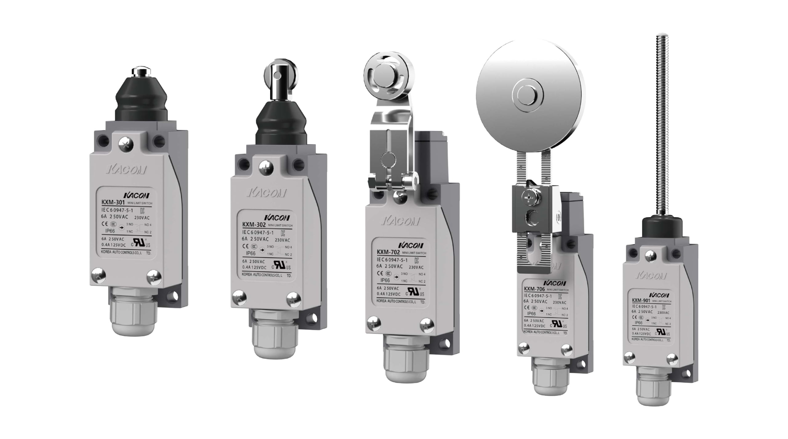
To eliminate false open faults in automated control loops, Kacon builds precision industrial limit switches equipped with Ag alloy / 24K Au Plate (gold-plated) contacts.
Because gold is chemically inert, it does not form insulating oxide layers. Kacon gold-plated contact interfaces maintain ultra-low contact resistance , delivering immediate signal recognition to 24V DC PLC input cards across millions of operating cycles.
5. Industry Limit Switch Brand Comparison Matrix
When selecting limit switches to prevent open-circuit faults and meet ingress protection requirements, evaluate key technical specs across major manufacturers:
| Brand / Manufacturer | Key Series | Housing & Protection | Contact Material Options | Best Suited Applications |
|---|---|---|---|---|
| Kacon | ZXG, KXM, KXL, ELN | Thermoplastic (IP65/66) to Aluminum Die-Cast (IP67/68) | Silver alloy / 24K Au Plate (Gold-plated available) | Low-load PLC loops, industrial automation, harsh washdown zones |
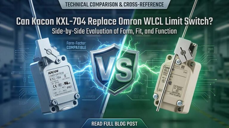
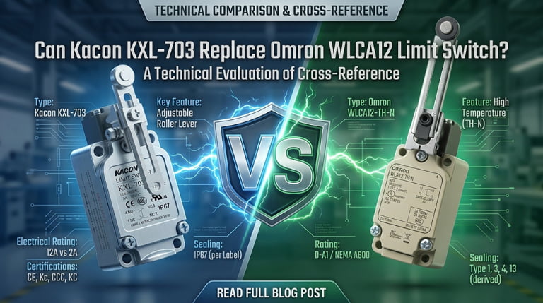
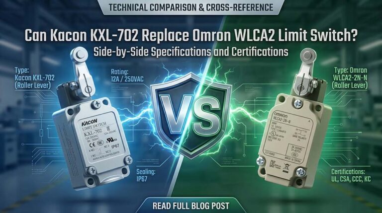
| Omron | D4CC, WL | Metal / Plastic (IP67) | Standard Silver alloy | General factory automation, machine tools |
| IDEC | HS Series, FC Series | Plastic / Metal (IP67) | Standard Silver alloy | Safety interlocks, machine control panels |
| Schneider Electric | Telemecanique (OsiSense XC) | Metal / Plastic (IP66/IP67) | Standard Silver alloy | Heavy-duty industrial machinery, conveyors |
| Autonics | CT, CL Series | Plastic / Aluminum (IP67) | Standard Silver alloy | Standard factory automation, packaging lines |
6. Quick Diagnostic Summary Matrix
Use this reference summary to cross-check visual, multimeter, and PLC status indicators when confirming an open limit switch circuit:
| Diagnostic Method | “OPEN” Indication (NO Contact) | “OPEN” Indication (NC Contact) | Circuit Impact |
|---|---|---|---|
| Mechanical / Visual | Actuator resting (untouched) | Actuator depressed by machine | Physical gap separates contact bridge |
| Multimeter (Unpowered) | Reads O.L (Infinity, No Tone) | Reads O.L (Infinity, No Tone) | Infinite resistance; complete signal interruption |
| PLC Input LED (Powered) | Status LED is OFF | Status LED is OFF | 0V DC reaching input terminal; logic state FALSE |
| Kacon Solution | Clean O.L open; flawless ~0 $\Omega$ closed | Clean O.L open; flawless ~0 $\Omega$ closed | 24K gold plating eliminates oxidation and false opens |
Conclusion: Precise Diagnostics Minimize Downtime
Determining whether a limit switch is open requires combining physical actuator inspection with electrical multimeter tests and PLC logic verification. Identifying open circuits accurately isolates system faults and reduces unplanned machine downtime.
To keep automated control loops running smoothly without false open interruptions, specify micro-load-optimized hardware equipped with 24K gold-plated contacts, such as the Kacon ZXG and KXM limit switch series.
External Technical References & Standards
For further technical specifications, safety standards, and multimeter testing techniques, consult the following resources:
- Electrical Safety Foundation International (ESFI) Workplace Safety Guidelines
- Fluke Official Application Guide: How to Test for Electrical Continuity
- OSHA Standard 1910.147 – Control of Hazardous Energy (Lockout/Tagout)
- ISO 13849-1 Safety of Machinery – Safety-Related Parts of Control Systems
- NEMA 250 Enclosures for Electrical Equipment Specifications