
In the heart of an automated production line, consistency is everything. Every machine component operates in a carefully orchestrated loop, depending heavily on accurate feedback signals. However, even the most advanced manufacturing setups can be brought to a sudden, grinding halt by the failure of a seemingly minor electromechanical component: the limit switch.
Understanding the Root Causes of Limit Switch Failures
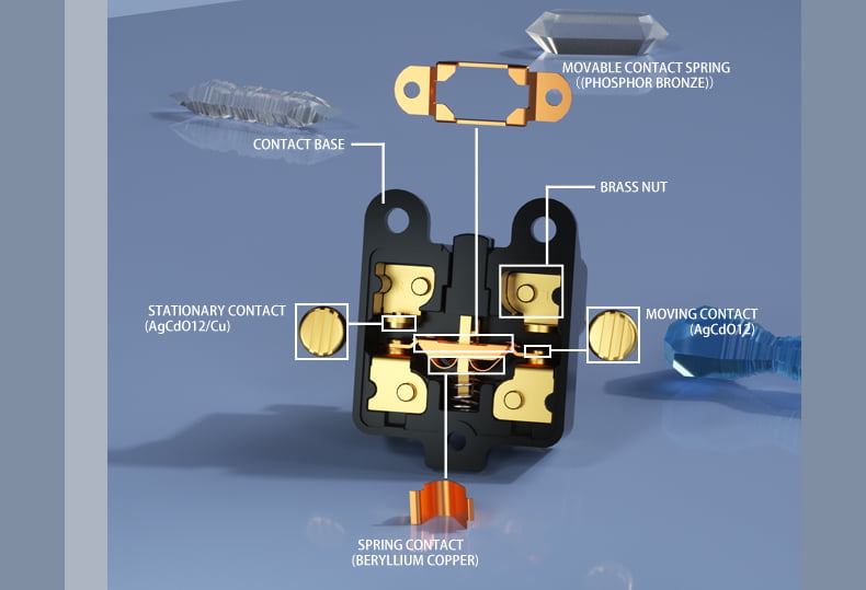
Before diving into the symptoms, it is crucial to recognize that a limit switch is a hybrid component. It relies on a physical mechanism (the actuator head and internal spring) to trigger an electrical mechanism (the internal contact blocks). Therefore, faults generally fall into two categories: mechanical wear and electrical breakdown.
International component safety standards, such as the IEC 60947-5-1 standard for low-voltage control devices, mandate rigorous design rules for these safety-critical components. However, sustained industrial stress, harsh environment exposure, and mechanical shock will inevitably cause components to degrade over millions of operational cycles.
5 Early Warning Signs of a Faulty Limit Switch
If you notice any of the following operational anomalies, your limit switch is likely nearing the end of its lifespan and requires immediate inspection or replacement.
1. Sluggish Actuator Return or Sticking Mechanisms
One of the most obvious indicators of mechanical failure is a sluggish or sticking actuator arm. When the target object moves away, the internal return spring should instantly snap the actuator back to its original resting state. If the lever arm delays or remains partially depressed, the internal contacts will fail to reset.
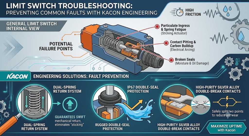
- Common Cause: This is typically caused by the ingress of fine particulate matter, cutting fluids, or grease that has hardened over time. It can also stem from internal spring fatigue after surpassing the manufacturer’s rated mechanical life cycle.
2. Erratic, Intermittent, or Flickering Control Signals
If your Programmable Logic Controller (PLC) displays intermittent input signals, or if a machine unexpectedly drops out of its automatic cycle without a clear fault code, the limit switch contacts are likely compromised.
- Common Cause: Electrical arcing occurs naturally over time, especially when switching heavy inductive electrical loads. This arcing leads to contact pitting or the buildup of a non-conductive carbon oxide layer on the contact surfaces, creating unstable contact resistance.
3. Physical Cracking or Seal Ingress on the Enclosure
A simple physical walk-through can reveal significant issues. Inspect the outer casing—whether it is constructed from high-tensile thermoplastic or zinc alloy. Look for small hairline cracks around the mounting holes or the conduit entry.
- Common Cause: Heavy mechanical impacts or extreme physical vibrations from nearby motors can fracture the housing. Once the structural integrity of the shell is lost, it can no longer maintain its NEMA enclosure standards or IP ratings, allowing water, humidity, and oils to seep directly into the electrical compartment.
4. Abnormal Heat Dissipation or Audible Buzzing
Under normal operating conditions, a low-voltage limit switch should run cool and remain silent. If you touch the switch housing during a scheduled maintenance shutdown and find it noticeably hot, or if you hear a faint buzzing sound while the machine is idling, you are looking at an active electrical fault.
- Common Cause: High contact resistance causes localized heating due to Joule heating, calculated by the formula $P = I^2R$. Audible buzzing usually points to loose wiring terminals or a loose contact block inside the switch vibrating under AC current.
5. Mechanical Misalignment and Loose Mounting
Sometimes, the switch itself is functional, but the installation is compromised. If a limit switch is missing its target or the lever arm is striking the cam at an incorrect angle, the switch will experience accelerated physical wear.
- Common Cause: Continuous machine vibration can slowly loosen mounting bolts. If the target cam strikes a roller lever arm at an angle steeper than 45 degrees, it exerts a destructive lateral force that will quickly bend the actuator shaft.
The Kacon Engineering Advantage: Designing Out Common Faults
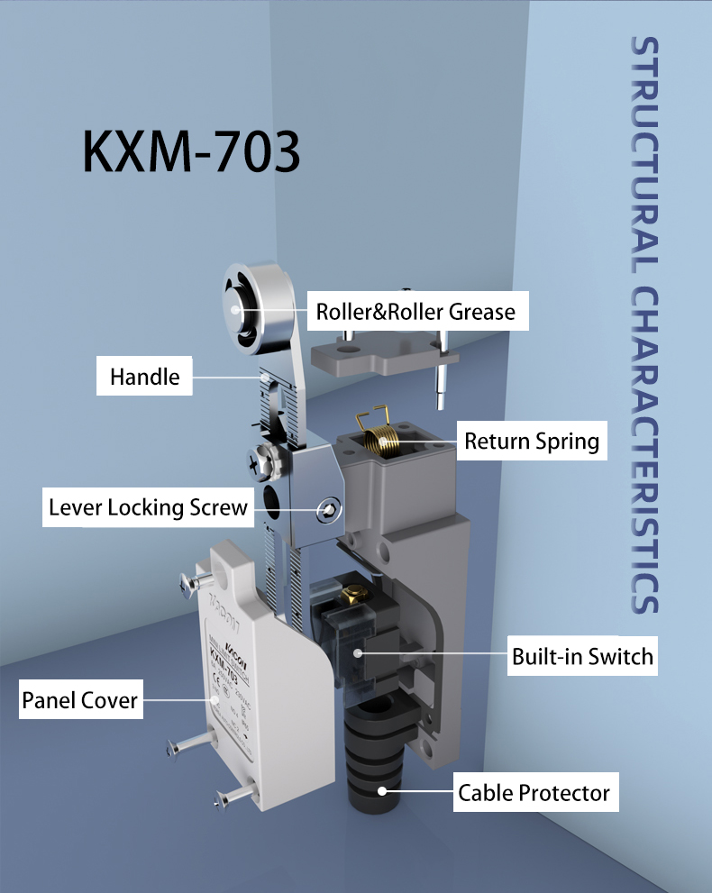
While understanding troubleshooting protocols is vital, the most cost-effective way to manage limit switch faults is to prevent them from occurring in the first place through superior component engineering. At Kacon, we have analyzed physical and electrical failure modes to engineer specific, high-durability solutions directly into our product lines:
- Dual-Spring Snap-Action Mechanism (No More Sticking Actuators): To eliminate the risk of sluggish returns or stuck actuators, Kacon limit switches utilize a robust, high-fatigue internal dual-spring tension system. Even under heavy vibration or continuous high-cycle operations, this architecture guarantees a swift, positive mechanical snap-action return, offering an industry-leading mechanical lifespan of up to 10 to 15 million cycles.
- IP67 Double-Seal & Oil-Resistant Protection (Combating Ingress): Standard seals degrade quickly when exposed to aggressive industrial cutting oils or synthetic coolants. Kacon addresses this by incorporating specialized, highly resilient NBR (Nitrile Butadiene Rubber) diaphragm seals and double-gasketed terminal wiring compartments. This secures a certified IP67 ingress rating, completely isolating the internal electrical contact block from moisture, dust, and corrosive chemicals.
- High-Purity Silver Alloy Double-Break Contacts (Eliminating Electrical Arcing): To handle the electrical spikes caused by inductive loads, Kacon switches feature premium silver-alloy contacts in a dual-circuit, double-break (Zb) contact structure. This configuration splits the arc energy across two physical points during break, drastically reducing electrical wear, preventing contact welding, and maintaining exceptionally low contact resistance.
- Vibration-Resistant Self-Lifting Terminals (Preventing Loose Wiring): Machine vibrations are a leading cause of signal flickering and loose screws. Kacon integrates self-lifting, captive-screw clamp terminals that lock the wiring tightly in place, ensuring your electrical connections remain secure and minimizing manual maintenance intervals.
Step-by-Step Diagnostic Matrix: Symptoms vs. Root Causes
To help your maintenance team quickly diagnose field issues, use this comparative guide to map observed machine behaviors to their mechanical or electrical root causes:
| Observed Symptom | Likely Fault Type | Primary Root Cause | Recommended Corrective Action | Kacon Prevention Feature |
|---|---|---|---|---|
| PLC misses input signal entirely | Electrical | Open circuit caused by welded contacts or severed wiring terminal. | Perform electrical continuity test; replace contact block. | Double-Break Silver Contacts prevent welding under high current. |
| Actuator does not snap back | Mechanical | Internal return spring failure or severe particle jam in head. | Replace actuator assembly or install a switch with higher ingress protection. | Dual-Spring Return System ensures high snap tension and rapid reset. |
| Intermittent signal during vibration | Electrical / Mechanical | Loose terminal screws or worn mounting brackets causing physical shifting. | Tighten all terminal screws to torque specifications; secure mounting base. | Self-Lifting Terminals resist loosening from heavy industrial vibration. |
| Burning smell or melted housing | Electrical | Severe overcurrent or arc tracking from using incorrect inductive load rating. | Check electrical load matching; install an arc suppressor or heavy-duty switch. | Zinc Alloy & Glass-Reinforced Enclosures offer excellent heat dispersion. |
| Moisture inside the wire conduit | Environmental | Damaged conduit seal or cracked rubber gland on the switch enclosure. | Replace the cable gland and ensure compliance with IEC IP67/IP69K sealing rules. | NBR Diaphragm Sealing blocks fluid tracking into the terminal box. |
How to Correctly Test a Limit Switch Using a Multimeter
If you suspect a limit switch is failing, do not guess. Follow this standard diagnostic procedure to verify its functionality.
⚠️ Safety Warning: Before performing any electrical diagnostic tests on automated machinery, ensure you follow all corporate OSHA Lockout/Tagout (LOTO) safety protocols to isolate hazardous energy and prevent accidental machine startup.
Step 1: Visual and Mechanical Pre-Check
With power disconnected, manually depress the actuator head. The movement should feel entirely smooth. Listen closely for a crisp, distinct mechanical “click” sound. This click indicates that the internal snap-action mechanism is transitioning successfully. If the movement feels gritty or silent, replace the switch head.
Step 2: Electrical Continuity Testing
Set your digital multimeter (DMM) to the Continuity Mode (indicated by a sound wave symbol). For a comprehensive guide on utilizing these diagnostic features safely, consult the official multimeter continuity testing instructions.
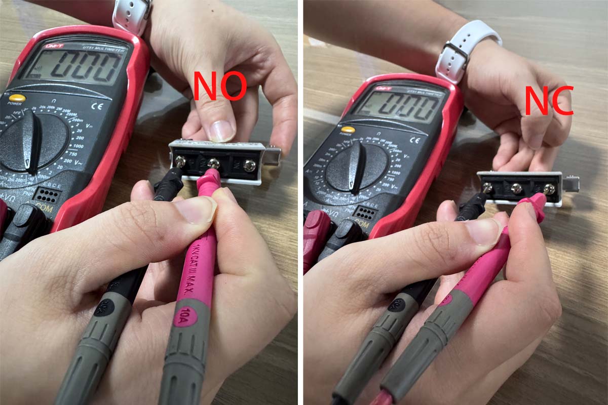
- Test the Normally Closed (NC) Terminals: Attach the multimeter leads to the NC terminals (usually marked 11 and 12, or 21 and 22). The meter should beep instantly, indicating a complete circuit. Manually press the actuator arm—the beep must stop immediately.
- Test the Normally Open (NO) Terminals: Move your leads to the NO terminals (marked 13 and 14). The meter should remain completely silent. Manually press the actuator arm—the meter should instantly beep, confirming a clean circuit completion.
If the meter fails to beep during these transitions, or if the measured resistance across closed contacts reads higher than a few ohms, the internal contacts are degraded and the switch must be replaced.
Conclusion: Prevent Costly Downtime with Proactive Testing
Identifying potential faults in a limit switch before they cause catastrophic failure is a cornerstone of modern predictive and preventive maintenance frameworks. By tracking physical housing wear, listening for strange noises, checking signal consistency, and executing regular multimeter audits, you can intercept problems early.
Investing in high-quality, properly rated electromechanical components suited for your specific workplace environment will drastically minimize unexpected component failures. Choosing premium hardware engineered to resist these failure modes—such as the double-sealed, dual-spring limit switches from Kacon—keeps your factory floor productive, safe, and efficient for the long haul.