
In the world of industrial automation, it’s often the smallest components that carry the heaviest responsibilities. Picture this: a high-speed packaging line is running flawlessly, processing thousands of units per hour, when suddenly, a single carriage overtravels. The machine jams, the line grinds to a halt, and technicians scramble. The culprit? A tiny, worn-out limit switch that was poorly specified for the job.
Factor 1: Actuator Mechanisms & Application Dynamics
The first step in limit switch selection is deciding how the switch will physically interact with your machinery. This physical interface is called the actuator. Choosing the wrong actuator type leads to premature mechanical wear, sluggish response times, or catastrophic physical damage to the switch itself.
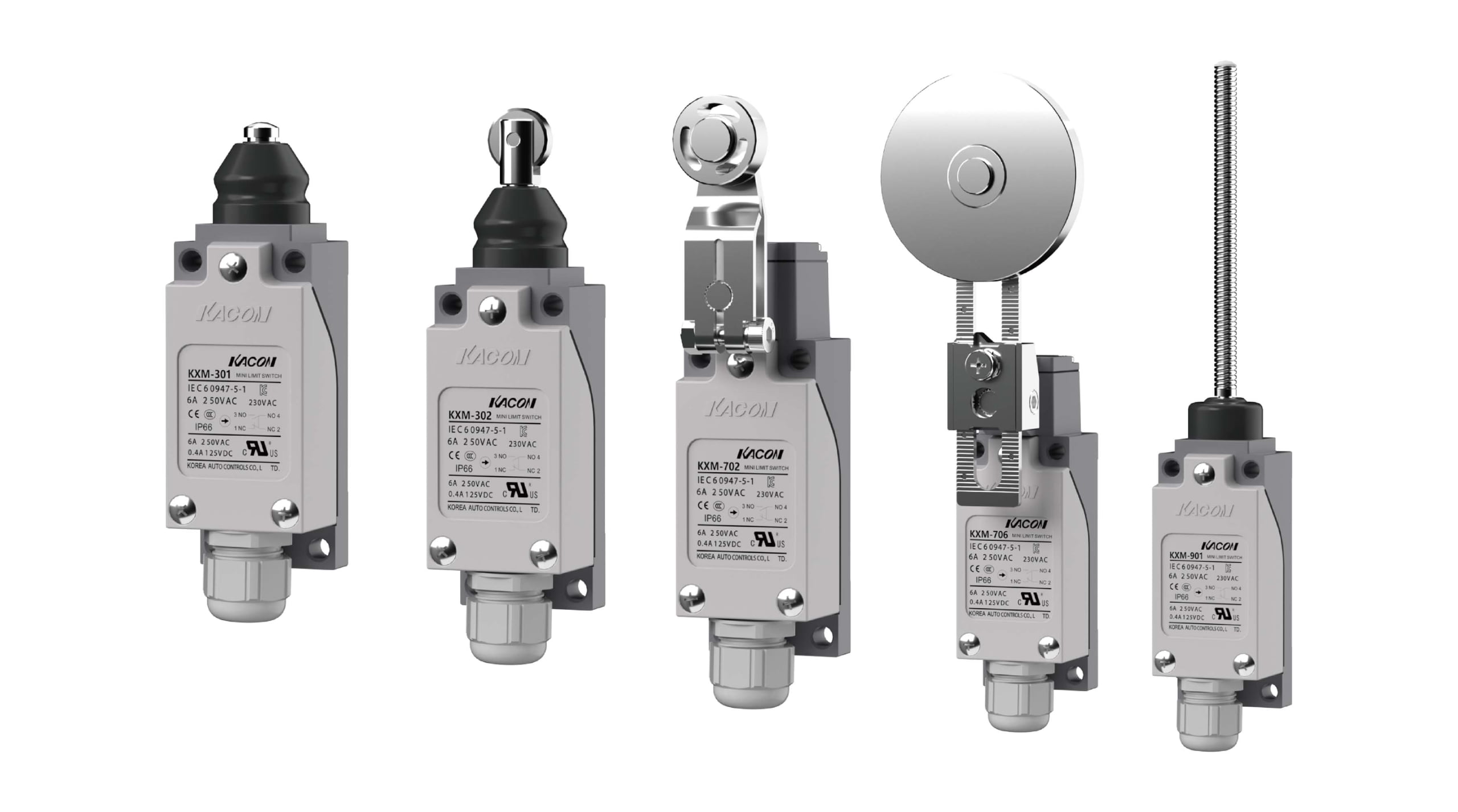
To match your limit switch with your machine’s motion profile, consider these three dominant actuator classes:
1. Plungers (Linear Motion)
Plunger actuators are designed for short, high-precision, unidirectional linear movements. They are activated when a machine part pushes directly down on the plunger.
- Best For: Verifying the closed position of heavy safety gates, press machines, or mold plates.
- Selection Tip: Ensure the actuating force acts in a strictly perpendicular direction to the plunger head. Side-loading or angular force will bend the plunger shaft and cause the switch to stick.
2. Roller Levers (Rotational & Cam-Driven Motion)
The roller lever is the workhorse of the industrial limit switch world. It features a wheel on the end of an arm that rotates when struck by a moving cam or slide. The rolling action minimizes friction, converting lateral motion into the downward force needed to trip the switch contacts.
- Best For: Conveyor lines, rotary indexes, and tracking sliding components where the direction of travel is parallel to the switch mounting.
- Selection Tip: Calculate the approach angle of your cam. If the cam strikes the lever too steeply, it can snap the arm. Aim for a smooth approach angle, typically between 30° and 45°.
3. Whisker/Flexible Rods (Multidirectional & Lightweight Motion)
Also known as “cat whisker” switches, these actuators feature a long, flexible spring-rod that can be tripped by physical contact from virtually any angle (360 degrees of activation).
- Best For: Detecting irregularly shaped packages on a conveyor belt, counting lightweight plastic bottles, or sensing wind-blown materials.
- Selection Tip: Do not use whisker switches in heavy-duty structural stopping applications. They are designed for detection, not for absorbing mechanical impact.
Factor 2: Environmental Conditions & Durability Standards
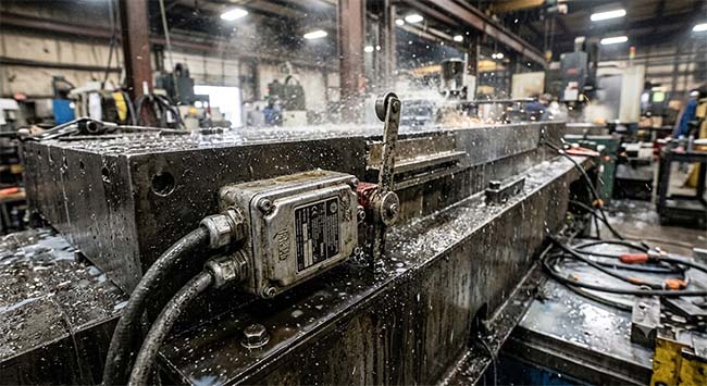
Industrial environments are rarely clean, dry, or climate-controlled. Dust, moisture, cutting oils, corrosive chemicals, and extreme temperatures will quickly destroy an inadequately protected limit switch. To ensure longevity, you must evaluate the environmental conditions of your specific application.
IP Ratings: Your Shield Against Dust and Liquids
Ingress Protection (IP) ratings define how well a switch casing prevents foreign objects and moisture from reaching its internal electrical contacts.
- IP65: Dust-tight and protected against low-pressure water jets. Ideal for standard indoor warehouse environments.
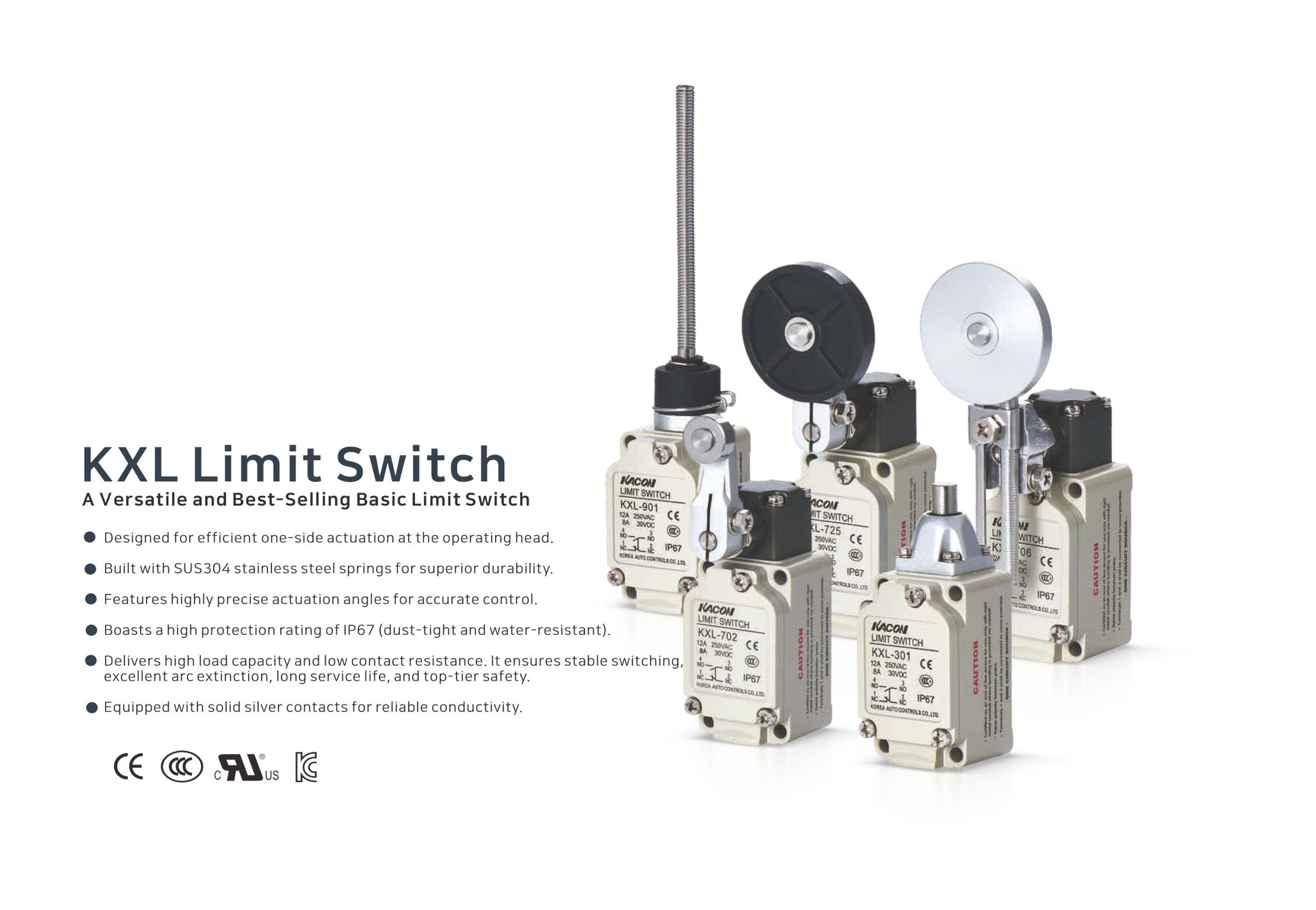
- IP67: Fully dust-tight and capable of surviving temporary immersion in water (up to 1 meter deep for 30 minutes). Perfect for outdoor machinery exposed to rain or washdown areas.
- IP69K: The gold standard for extreme environments. It protects against high-pressure, high-temperature washdowns. This is mandatory in food processing, pharmaceutical manufacturing, and heavy off-road construction equipment where steam cleaning is standard. For a deeper understanding of these sealing standards, you can refer to the official IEC Ingress Protection (IP) Ratings Guide.
Housing Material: Plastic vs. Metal
Choosing the right shell is a balance between budget and durability:
- Plastic (Thermoplastic) Housings: Highly resistant to chemical corrosion, lightweight, and incredibly cost-effective. They are excellent for standard assembly lines, packaging, and non-impact environments.
- Metal (Zinc/Aluminum Alloy) Housings: Engineered for heavy-duty environments. They resist intense mechanical impacts, abrasive dust (like mining or cement facilities), and weld spatter. To compare physical enclosure protection standards in North America, engineers often consult the NEMA Enclosure Standards alongside IP ratings.
Factor 3: Electrical Specifications & Wiring Compatibility
The finest mechanical actuator and the toughest metal housing won’t matter if the electrical contacts inside burn out after a week. You must carefully match the limit switch’s internal electrical specifications with your control system’s requirements.
Inductive vs. Resistive Loads
Never assume a limit switch rated for “10 Amps” can handle any 10-Amp load. You must distinguish between:
- Resistive Loads: Simple loads like heaters or indicator lights. They draw a steady, predictable current.
- Inductive Loads: Devices with coils, such as electric motors, solenoids, or relays. When an inductive load is disconnected, the magnetic field collapses, creating a massive high-voltage spike (known as arcing) across the switch contacts.
If your system uses high-voltage inductive loads, choose a limit switch with heavy-duty contacts (often silver-alloy) or integrate external arc-suppression circuits to prevent the contacts from welding shut. Detailed circuit protection guidelines for switching inductive loads can be found on the IEEE Xplore Digital Library under contact arc suppression standards.
Contact Configuration: NO vs. NC
Ensure you understand the logic your PLC (Programmable Logic Controller) or safety circuit requires:
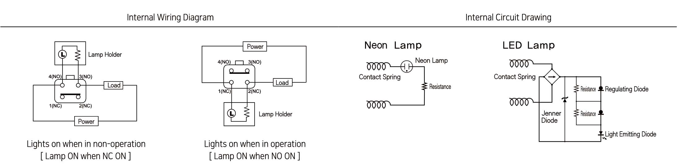
- Normally Open (NO): The circuit is disconnected until the actuator is pressed, closing the circuit and sending a signal.
- Normally Closed (NC): The circuit is continuous until the actuator is pressed, breaking the circuit.
- Safety First: For critical safety and emergency stop applications, always use Normally Closed (NC) contacts. If a wire breaks or a connection fails in an NC loop, the system will immediately detect the open circuit and shut down safely (fail-safe design). This design is mandated by many international machine safeguarding regulations, such as those outlined by the OSHA Machine Guarding Standards and the European ISO 13849 Safety-Related Parts of Control Systems.
Summary Comparison Table
To help you visualize your options, here is a quick reference table matching applications to their ideal limit switch configurations based on ANSI Industrial Standard Classifications:
| Application | Actuator Type | Housing Material | Ingress Protection | Contact Priority |
|---|---|---|---|---|
| Food & Beverage Washdown | Roller Lever | Stainless Steel / Plastic | IP69K | NC (Safety Interlock) |
| Standard Conveyor Counting | Roller Lever or Whisker | Thermoplastic | IP65 | NO (Signal Input) |
| Heavy Machining/CNC Mills | Plunger | Metal Alloy | IP67 (Coolant resistant) | NC (Overtravel Stop) |
| Outdoor Crane Positioning | Heavy-Duty Roller Arm | Metal Alloy | IP67 | NC (End-of-travel) |
Conclusion:
Selecting a limit switch doesn’t have to be a guessing game. By methodically assessing your actuation mechanics, evaluating the environmental hazards, and locking down your electrical load requirements, you ensure that your selected component will survive millions of cycles without breaking a sweat.
Investing a little extra time during the design and procurement phase to verify these three pillars will reward you with a highly reliable machine, minimal downtime, and peace of mind.