
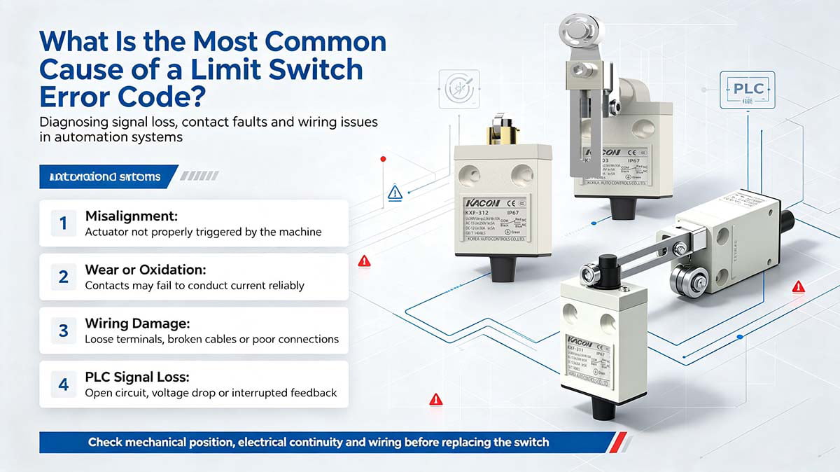
While physical breakage is often the immediate suspect during emergency maintenance, the root cause usually stems from three distinct categories: mechanical misalignment, environmental ingress, and the most common hidden culprit—contact oxidation on 24V DC low-voltage PLC circuits. Below is a detailed technical analysis of these failure modes and how to resolve them permanently.
Cause 1 of a Limit Switch Error Code: Mechanical Misalignment & Wear (The Physical Culprit)
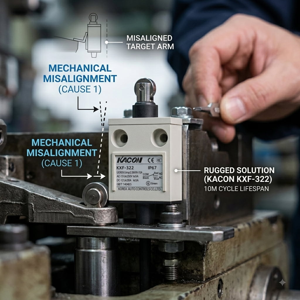
Before opening any electrical junction boxes, maintenance engineers should inspect the physical relationship between the actuator and the target. In high-vibration manufacturing environments, mechanical alignment between the limit switch actuator (such as a roller lever, plunger, or wobble stick) and the moving machine cam can shift over time.
- The Problem: The machine component hits the switch arm at an incorrect angle, fails to depress the plunger far enough to reach the operating point, or the actuator arm vibrates loose. The PLC never receives the “closed” signal before its internal timer expires, generating a position error code.
- Diagnostic & Action Steps: Realign mounting brackets, verify travel tolerances against standardized switch specifications like IEC 60947-5-1 Low-Voltage Switchgear and Controlgear, and ensure the operating cam depress depth matches manufacturer limits.
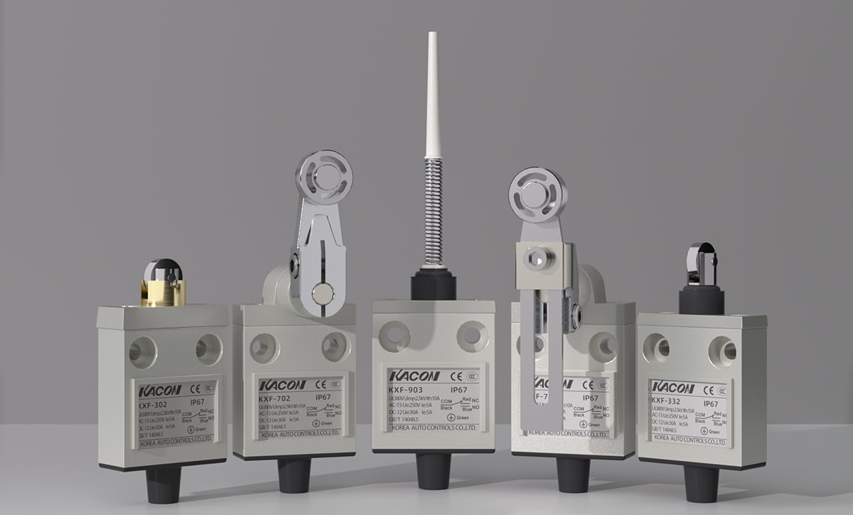
- Hardware Upgrade: If heavy mechanical vibration repeatedly loosens switches, upgrade to ruggedized industrial hardware. Heavy-duty units, such as the Kacon KXF Series, feature die-cast aluminum housings and reinforced internal mechanisms designed to absorb heavy impacts while maintaining strict alignment across a 10,000,000-cycle mechanical lifespan.
Cause 2 of a Limit Switch Error Code: Environmental Ingress (The Fluid & Dust Culprit)
Industrial limit switches operate under demanding environmental conditions. When a CNC machining center, stamping press, or outdoor conveyor throws a sudden error code, liquid or particulate contamination inside the switch body is frequently the root cause.
- The Problem: Coolant, hydraulic oil, airborne moisture, or fine metal dust bypasses worn rubber seals or improper cable glands. Once inside the contact block, fluid can short-circuit the terminals (causing a false closed signal) or corrode internal wiring blocks entirely (causing an open circuit signal).
- Diagnostic & Action Steps: Verify that the enclosure protection level matches the installation environment. While basic automation tasks can utilize IP65 plastic housings (such as the Kacon KXN Series), high-pressure washdown areas or heavy coolant immersion zones demand IP67 or IP68 rated enclosures.
- Standards Compliance: Verify enclosure ratings against recognized standards, such as NEMA 250 Specifications for Electrical Enclosures and international IEC IP Rating Standards, to ensure long-term fluid protection.
Cause 3 of a Limit Switch Error Code: Contact Oxidation (The Most Common “Hidden” Culprit)
If the switch is aligned correctly, the housing interior is completely dry, and the lever clicks smoothly when manually actuated—yet the PLC still logs a “Sensor Open” or “Signal Lost” fault—you are likely facing the most common electrical failure in modern automation: False Open caused by contact oxidation.
Why Oxidation Causes Error Codes in 24V DC PLC Circuits
Decades ago, field limit switches carried high-voltage AC current (110V/220V) to directly control motor contactors. This higher power generated a small electrical arc upon contact closure, which naturally burned off surface contaminants and oxidation from standard silver alloy contacts.
Modern automated control architecture, however, connects field limit switches directly to low-voltage PLC input channels operating on micro-loads (typically 24V DC at currents under 10 mA):
- Because the micro-load signal carries very little electrical energy, no self-cleaning arc is created upon contact closure.
- Over time, exposure to ambient air and humidity forms a microscopic oxide or tarnish layer on standard silver-alloy contacts.
- When the switch closes mechanically, the 24V DC micro-current lacks the voltage energy to pierce this non-conductive oxide film.
- The Result: The contact resistance rises . The PLC reads 0V DC at its input module, interprets the line as an open circuit or broken safety loop, and instantly trips an emergency stop or error code. For proper measurement methods, consult Fluke’s Guide to Electrical Continuity Testing.
Eliminating False Opens with Kacon 24K Gold-Plated Contacts
To eliminate micro-load signal loss, limit switches installed on low-current PLC input loops must utilize contact materials engineered specifically for dry-circuit operation.
Kacon solves this micro-load vulnerability by equipping high-precision limit switches—such as the ZXG and KXM series—with Ag alloy / 24K Au Plate (gold-plated) contacts. Because gold is chemically inert, it does not form oxide or tarnish layers under ambient industrial conditions.
Even after millions of micro-load operating cycles, gold-plated contacts maintain ultra-low contact resistance , guaranteeing immediate, reliable 24V DC signal transmission without triggering false PLC errors.
Diagnostic Matrix: Decoding Your Limit Switch Error
Use this reference table to systematically match error symptoms on your HMI/PLC screen with the most likely root cause and practical corrective action:
| Error Symptom on HMI / PLC | Physical & Visual Inspection Result | Most Likely Root Cause | Recommended Corrective Action |
|---|---|---|---|
| “Overtravel Fault” / “Position Not Reached” | Actuator arm is bent, loose, or misses machine target cam. | Mechanical misalignment or excessive mechanical shock damage. | Realign target cam; upgrade to die-cast aluminum Kacon KXL Series. |
| “Short Circuit” / “Erratic Signal” | Housing is cracked, loose cable gland, or internal oil/water ingress. | Environmental Ingress (IP rating failure or worn enclosure seal). | Replace switch; install IP67/IP68 rated unit with proper liquid-tight cable seals. |
| “Safety Loop Open” / “Signal Lost” | Switch actuates click-smoothly, housing dry, multimeter reads high resistance. | Contact Oxidation (Micro-Load Failure) blocking 24V DC PLC signal. | Upgrade contact block to Kacon ZXG / KXM Series with 24K Gold-Plated contacts. |
| “Simultaneous NO/NC Fault” | Multimeter shows unstable or intermittent resistance on both NO and NC terminals. | Internal mechanical fatigue (broken return spring or worn contact bridge). | Replace damaged unit; verify machinery safety standards per ISO 13849-1 Machine Safety Guidelines. |
Conclusion: Eliminating False Error Codes in Automation
When a limit switch error code appears on an HMI screen, it indicates a breakdown in the physical-to-electrical signal chain. While mechanical alignment issues and fluid ingress are visual defects that maintenance teams can easily spot, contact oxidation remains the single most common, invisible source of unexpected downtime on 24V DC PLC lines.
By understanding these failure modes and specifying micro-load optimized hardware—such as Kacon gold-plated and heavy-duty limit switches—automation engineers can eliminate false error signals, maintain high diagnostic accuracy, and optimize overall equipment effectiveness (OEE).
External Technical References & Standards
For further technical specifications on switch ratings, functional safety, and testing methods, refer to the following authoritative resources:
- IEC 60947-5-1 Specifications for Low-Voltage Switchgear and Controlgear
- NEMA 250 Specification Standard for Electrical Equipment Enclosures
- IEC IP (Ingress Protection) Enclosure Rating Standards
- ISO 13849-1 Safety of Machinery – Safety-Related Parts of Control Systems
- Fluke Technical Guide: Testing Electrical Continuity with Digital Multimeters