
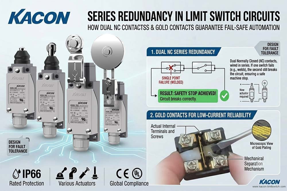
- Failure Mode A (Intermittent “Phantom” Stops): The 24 VDC / 8 mA signal from the PLC input was too weak to break through the thin layer of silver oxidation that naturally formed on the contacts over time (“fretting corrosion”). This caused sudden, unexplained emergency stops during normal production.
- Failure Mode B (Near-Miss Crash): During an overspeed condition, a high electrical spike caused the silver contacts inside the limit switch to micro-weld together. When the gantry reached the end of travel, the contact failed to open. The PLC never received the stop signal, causing the gantry to hit the mechanical stops at full speed, resulting in $45,000 in mechanical damage and 14 hours of downtime.
Understanding how to properly design series redundant limit switch loops, spacing the physical switches correctly, and selecting switches with high-reliability gold-plated contacts (such as those engineered by Kacon) is essential for achieving compliance with global industrial safety standards.
The Principle of Series Redundancy with Dual NC Contacts
In a safety-critical control circuit, the functional goal is simple: if any fault, hazard, or overtravel condition occurs, power to the dangerous actuator (e.g., motor drive, hydraulic valve) must be immediately cut off.
How the Dual-Switch Loop Works
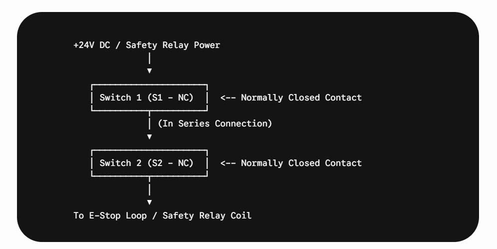
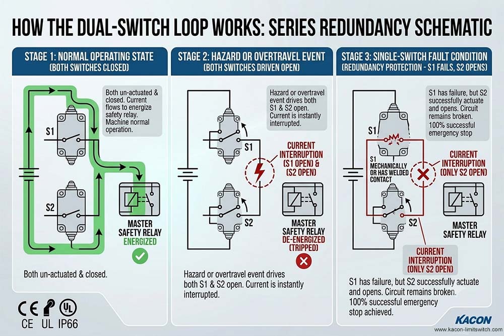
Two limit switches (S1 and S2), both utilizing Normally Closed (NC) contacts, are wired back-to-back in a series loop:
- Normal Operating State: Both S1 and S2 remain un-actuated and fully closed. Current flows unimpeded through the series loop to energize the master safety relay, allowing normal machine operation.
- Hazard or Overtravel Event: When a guard door opens or a machine axis overtravels, both switches are driven open. Current is instantly interrupted, tripping the safety relay and shutting down power.
- Single-Switch Fault Condition (Redundancy Protection): If Switch S1 mechanically jams or suffers a welded contact fault, Switch S2 will still actuate and physically open the circuit. Even with a 50% mechanical failure rate in the sensing loop, the system still achieves a 100% successful emergency stop.
Critical Installation Practice: Managing Physical Switch Spacing
While series redundancy solves electrical and single-switch mechanical faults, improper physical installation can completely defeat the redundant architecture.
When mounting dual limit switches (S1 and S2) on a single machine guard or slide rail, physical separation distance and mechanical actuation staggering are vital:
1. Avoiding Common-Cause Failures
If S1 and S2 are mounted directly adjacent to each other without proper spacing, a single mechanical impact (e.g., a loose metal chip, broken mounting bracket, or misaligned cam) can physically crush or jam both switches simultaneously. Spacing the switches ensures that a localized physical obstruction will not disable both sensing channels.
2. Staggered Actuation Dynamics
In high-safety designs compliant with standards like ISO 13849-1 for Safety-Related Parts of Control Systems and IEC 62061 for Functional Safety, switches S1 and S2 should be actuated sequentially or via independent mechanical cams:
- Primary Switch (S1): Actuates at the primary stop/safety threshold.
- Secondary Switch (S2): Actuates slightly deeper in the travel stroke as a true mechanical backup.
The Role of Gold-Plated Contacts in Low-Current Safety Loops
Redundant series wiring doubles the mechanical safety of your circuit, but it also doubles the total electrical contact resistance. In modern automated control systems where limit switches feed directly into 24 VDC PLC safety inputs or low-current safety relays (often operating at under 10 mA):
- Standard silver contacts rely on micro-arcing from higher currents to burn away surface oxidation.
- In low-voltage, low-current safety loops, silver contacts can develop an oxide film over time, causing false high-resistance readings that the safety relay interprets as an open-circuit fault.
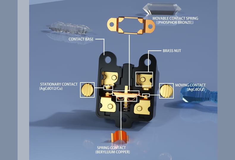
To solve this low-power switching issue, specifying switches with gold-plated contacts is mandatory for long-term signal stability. Gold is a noble metal that does not oxidize or corrode, guaranteeing near-zero contact resistance even after millions of low-current switching cycles. General guidelines on contact material selection can be explored in the IEEE Electrical Contacts Literature Standards.
Single NC vs. Redundant NC vs. Kacon Gold-Contact Redundancy
To help electrical engineers select the optimum safety setup, the following comparison matrix outlines performance across switch configurations:
| Design Criterion | Single NC Limit Switch | Standard Dual NC Series Redundancy | Kacon Gold-Contact Dual NC Series Redundancy |
|---|---|---|---|
| Mechanical Fault Tolerance | Zero (Single point of failure) | High (If one jams, the other opens) | High (If one jams, the other opens) |
| Contact Resistance Stability | Moderate (Prone to oxidation over time) | Low (Resistance doubles across 2 silver switches) | Maximum (Gold plating eliminates oxidation entirely) |
| Low-Current PLC Compatibility | Moderate | Poor (Risk of false oxidation trips) | Optimal (Ideal for 24V DC / <10mA Safety Inputs) |
| Common-Cause Failure Risk | N/A | High (If improperly spaced) | Low (When properly spaced with Kacon mounting accessories) |
| Safety System Compliance | Basic Category 1 / PL b | Category 3 / PL d | Up to Category 4 / PL e / SIL 3 |
Engineering Maximum Uptime with Kacon Limit Switches
When executing a series redundant safety design, hardware quality directly dictates your plant’s overall uptime. Kacon integrates industrial-grade precision and safety engineering into every position switch:
- 24K Gold-Plated Double-Break Contacts: Kacon’s safety and micro-switch ranges feature premium gold-plated contact bridges engineered specifically for low-voltage PLC and safety relay integration. This completely eliminates contact oxidation and erratic signal bounce.
- Positive Opening Operation: Kacon safety limit switches feature certified forced-disconnection linkages, ensuring that even under severe electrical fault conditions, mechanical force shear-breaks any potential contact binding.
- IP67 Rugged Enclosures: Housed in heavy-duty zinc-alloy die-cast casings with oil-resistant seals, Kacon switches withstand harsh washdown environments, abrasive dust, and heavy vibration without losing alignment.
Conclusion: Elevating Safety Through Redundancy and Quality
Designing a truly fail-safe machine requires a two-pronged approach: combining intelligent circuit architecture with premium hardware components. By implementing series redundancy with dual NC limit switches, enforcing proper physical mounting spacing, and specifying Kacon switches with gold-plated contacts, control engineers eliminate single-point mechanical risks while guaranteeing stable electrical feedback for millions of operational cycles.