
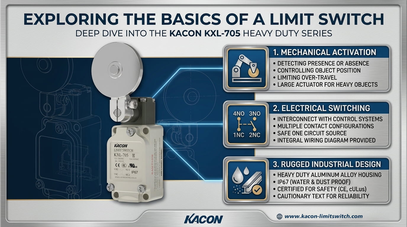
At its core, a limit switch is an electromechanical device consisting of an actuator mechanically linked to a set of internal electrical contacts. When a moving machine part or target object physically strikes the actuator, the contacts open or close, sending a discrete electrical signal to a control device such as a PLC or relay block.
Below, we explore the fundamentals of limit switches through a real-world client deployment case study, followed by a detailed breakdown of their core anatomy, terminal wiring rules, and engineering best practices.
1. Real-World Client Case Study: Getting Back to Basics on a Packaging Line
A prominent packaging machinery builder in North America was modernizing a high-speed cartooning line. During trial runs, the control system experienced mysterious, intermittent positioning faults that repeatedly halted production.
The Basic Oversight
Upon inspection by a senior applications engineer, the root cause was traced back to a fundamental misunderstanding of switch specifications and terminal wiring logic:
- The Wiring Error: Technicians had wired the primary safety position switches using their Normally Open (NO) terminals instead of Normally Closed (NC) fail-safe loops.
- The Contact Material Flaw: Furthermore, generic switches with standard silver contacts oxidized rapidly under the PLC’s low-voltage micro-load (24V DC at under 10 mA), generating “false open” fault codes.
The Kacon Technical Resolution
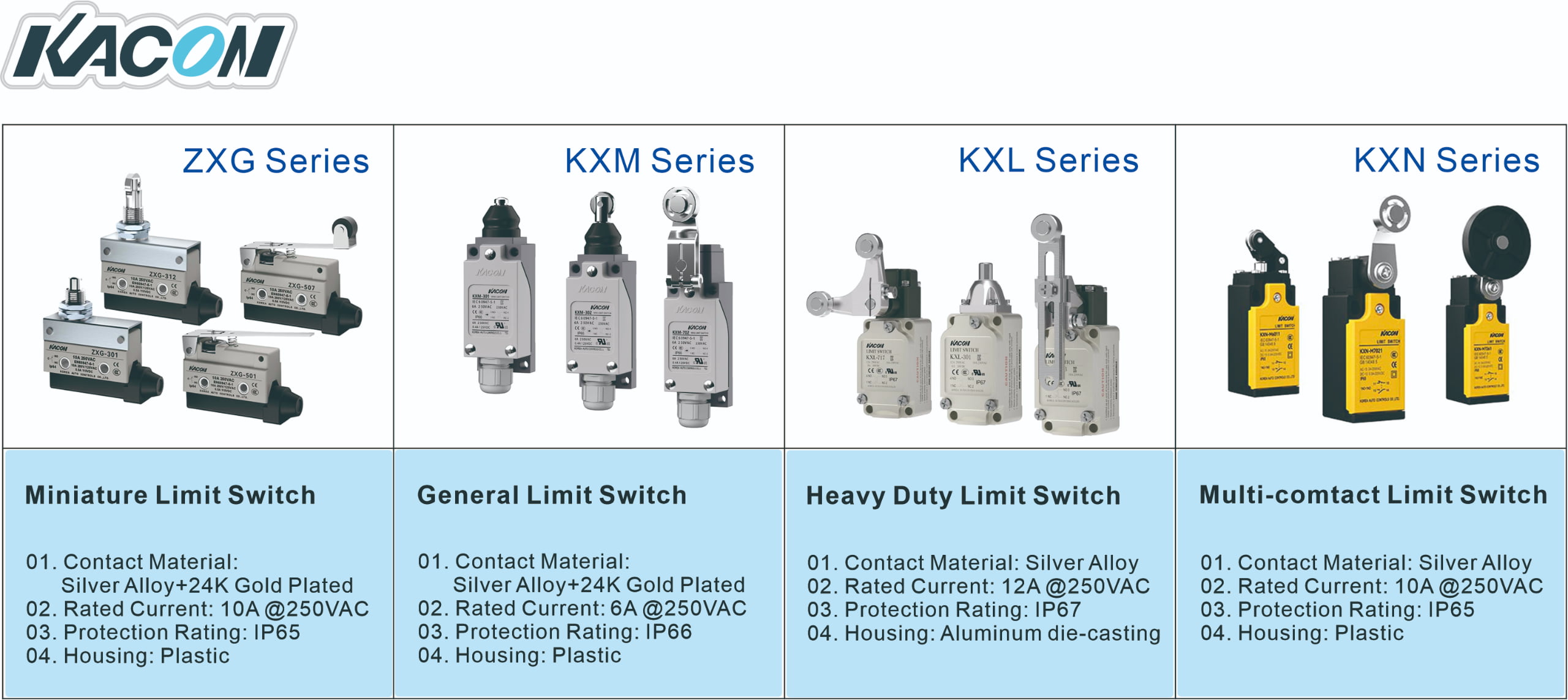
The engineering team returned to basics by partnering with Kacon. They replaced the generic switches with high-reliability industrial units from the Kacon ZXG and KXM series.
- Established proper 1NO + 1NC dual-circuit wiring for safety monitoring.
- Leveraged Ag alloy / 24K Au Plate (gold-plated) contacts to permanently eliminate micro-load contact oxidation.
These basic corrections restored absolute operational reliability, ensuring millions of trouble-free cycles.
2. The Core Anatomy of a Limit Switch
To understand how a limit switch functions, you must look at its three primary structural components:
1. The Actuator (Physical Trigger Mechanism)
The actuator is the external component that physically contacts the moving machine target. Common actuator styles include:
- Roller Levers: Ideal for sliding, rotating, or angled cam actuation paths.
- Pin / Push Plungers: Best for direct, straight-line pushing motions with strict travel tolerances.
- Wobble / Cat Whisker Levers: Flexible, multi-directional actuators ideal for conveyor package detection.
2. The Housing (Environmental Protection)
The outer enclosure shields internal components from dust, moisture, oil spray, and mechanical shock. Depending on the environment, housings range from engineered thermoplastic enclosures (IEC IP65/IP66 Ingress Ratings) to heavy-duty die-cast aluminum enclosures (NEMA 4X / IP67 Ratings) like the Kacon KXL series.
3. The Contact Block (Electrical Switching Circuit)
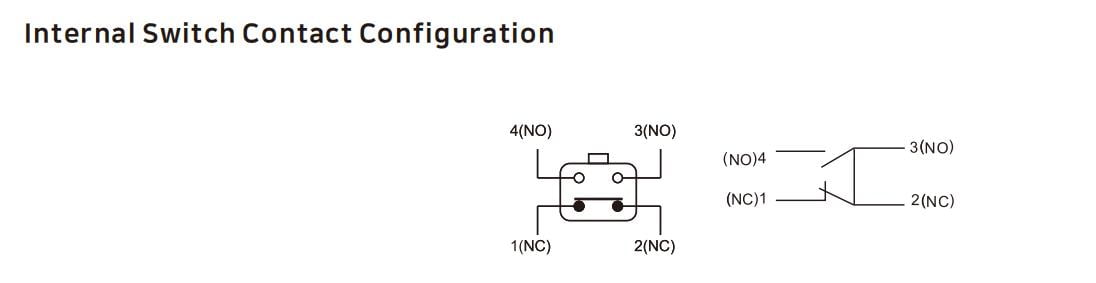
Inside the housing lies the switching mechanism. Standard industrial limit switches feature a 1NO + 1NC dual-circuit contact configuration, providing one Normally Open and one Normally Closed path driven by a fast snap-action mechanism designed in compliance with ISO 13849-1 Functional Safety Standards.
3. Fundamental Wiring Rules: COM, NC, and NO Terminals
Mastering limit switch installation requires understanding three core terminal designations:
- COM (Common): The main power feed terminal where the incoming power or signal wire connects.
- NC (Normally Closed): The circuit path that remains closed (conducting electricity) when the switch is at rest. Essential for fail-safe loops and safety interlocks.
- NO (Normally Open): The circuit path that remains open (non-conducting) at rest, closing only when the actuator is depressed. Used for sequence triggers and object counting.
Modern Engineering Rule: Overcoming Low-Load Oxidation
While legacy switches were designed for high-voltage AC loads (110V/220V), modern PLCs operate on low-voltage micro-loads (24V DC at under 10 mA).
- The Oxidation Risk: Low current cannot generate an electrical arc to burn off natural oxidation on standard silver alloy contacts. Over time, resistance rises, causing false open signals.
- The Kacon Solution: Switches like Kacon’s ZXG and KXM series utilize 24K gold-plated contacts. Gold resists chemical oxidation completely, ensuring zero-resistance connection stability verified through standard Fluke Multimeter Continuity Testing Methods. Circuit theory can be referenced at the IEEE Xplore Digital Library.
4. Summary Basics Matrix
Reference this summary table for quick comparison of limit switch fundamental principles:
| Basic Principle | What It Means | Industrial Best Practice |
|---|---|---|
| Function | Translates physical machine movement into an electrical signal. | Match the actuator type (roller lever vs. push plunger) to target movement motion. |
| Wiring Logic | Operates via COM, NC, and NO terminal connections. | Always wire emergency stops and safety loops to NC (Normally Closed) for fail-safe protection. |
| Polarity | Purely mechanical dry contacts with no electrical polarity. | Can be used interchangeably in AC and DC control loops. |
| Contact Reliability | Vulnerable to surface oxidation under low-voltage PLC micro-loads. | Specify Kacon 24K Gold-Plated Contacts to prevent micro-load signal loss. |
Conclusion: Mastering the Fundamentals
Understanding the basics of a limit switch—its mechanical anatomy, terminal logic, and contact behavior—is essential for any automation engineer or maintenance technician. By combining sound foundational wiring principles with heavy-duty, oxidation-resistant hardware from Kacon, industrial operators can maintain high machine precision, absolute functional safety, and maximum plant uptime.
External Technical References & Standards
For further reading on electrical standards, safety guidelines, and circuit testing procedures, explore these technical resources:
- IEC International Electrotechnical Commission – Low-Voltage Switchgear Standards
- ISO 13849-1 Machine Safety Guidelines for Control Systems
- NEMA 250 Enclosure Standards for Electrical Equipment
- IEEE Xplore Digital Library – Electrical Engineering Standards
- Fluke Technical Resource: Testing Electrical Continuity with Multimeters